
Common Base Configuration
Enroll to start learning
You’ve not yet enrolled in this course. Please enroll for free to listen to audio lessons, classroom podcasts and take practice test.
Interactive Audio Lesson
Listen to a student-teacher conversation explaining the topic in a relatable way.
Understanding Current Gain
🔒 Unlock Audio Lesson
Sign up and enroll to listen to this audio lesson

Let's begin by discussing the importance of current gain in a common base configuration. Do any of you know what current gain refers to?

Is it how much the transistor amplifies the input current?
Exactly! Current gain is the ratio of the output current to the input current. Can anyone tell me how we normally go about finding this current gain?

Do we short the output terminal to AC ground?
Correct! By shorting the output terminal, we eliminate its impact on the analysis. Now, why do we want to do this? What benefit does it provide?

It simplifies the calculations and shows the true performance of the circuit.
Absolutely! This allows us to focus purely on the amplification and observe how the current behaves under ideal conditions. Let's summarize that point: current gain reveals how efficiently a transistor amplifies inputs.
Mathematical Expressing of Gain
🔒 Unlock Audio Lesson
Sign up and enroll to listen to this audio lesson

Now, let's explore the mathematical expression we derive for current gain. Who can remind me of the key formula we use?

Isn’t it the ratio of output current to input current?
Exactly! Specifically, we can express the output current as a function of various components including the transconductance. What happens to the gain in terms of voltages?
The voltage drop across the emitter is important in determining the output current!
"Correct! We use the voltage and the gain formulas to relate these currents effectively. To summarize, we derive our current gain as ≈
Characteristics of Common Base Configuration
🔒 Unlock Audio Lesson
Sign up and enroll to listen to this audio lesson
Let's shift gears and discuss the characteristics of a common base configuration. What stands out about the input and output resistances?
The input resistance is low while the output resistance is high, right?
That's correct! This low input resistance allows the common base configuration to accept higher currents while maintaining a decent driving capability. Can you think of application areas where this might be advantageous?
Would it be good for buffering low-level signals?
Exactly! The common base acts as a buffer for current mode, ensuring that small changes in input current translate into appropriately larger changes in output current. Thus, due to its high output resistance and low input resistance, it serves effectively in driving loads.
Introduction & Overview
Read summaries of the section's main ideas at different levels of detail.
Quick Overview
Standard
This section details the operational principles and mathematical analysis of the common base transistor configuration. It examines the conditions required to derive current gain, as well as its similarities to the common gate configuration, highlighting its function as a buffer with specific input and output impedance characteristics.
Detailed
Common Base Configuration
The common base configuration is characterized by its transistor arrangement in which the base terminal is common to both input and output. This setup offers low input resistance, high output resistance, and a nearly unity current gain which makes it suitable for current amplification tasks.
Current Gain Derivation
To evaluate current gain, the output terminal is unloaded by shorting it to AC ground, allowing the current from the signal input to be observed without any impedance impact. The unloaded condition dictates that the input signal's terminating impedance approaches zero, which simplifies the mathematical modeling of the circuit.
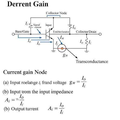
We analyze the collector node, often referred to as the output node, where the current gain is derived. This analysis leads to identifying contributions from various currents in the circuit, specifically:
1. The transconductance current, which relates directly to the emitter voltage.
2. Secondary currents influenced by any external resistances connected in the circuit.
3. The effective output current derived from the input signal.
The final mathematical expression for current gain reveals that it heavily depends on the transconductance (
g_m
) of the transistor and is expressed as the ratio of output current to input signal current.
The significance of this configuration lies in its ideal behavior for current buffers, where high output resistance and low input resistance enhance the ability to drive loads effectively. Such understanding also lays the groundwork for exploring current gain and output implications in common gate configurations and necessitates an appreciation of biasing strategies employed in practical applications.
Youtube Videos

Audio Book
Dive deep into the subject with an immersive audiobook experience.
Understanding Current Gain in Common Base Configuration
Chapter 1 of 5
🔒 Unlock Audio Chapter
Sign up and enroll to access the full audio experience
Chapter Content
So, here we do have the common base configuration. We do have the corresponding circuit here and to get the current gain what we have to do? At the output node we have to make their corresponding terminal unloaded. What do you mean by unloaded? We have to basically short this node to ac ground and then we have to find how much the current it is coming from the circuit signal current.
Detailed Explanation
In the common base configuration, the goal is to determine the current gain of the circuit. To do this, we need to ensure that the output node is 'unloaded,' which means connecting it directly to an AC ground. This setup allows us to analyze the current coming from the input signal without external influence.
Examples & Analogies
Imagine trying to measure the water flow from a hose. To get an accurate measurement, you need to ensure that the hose's outlet is not blocked and is open to the air. Similarly, by making the output node unloaded, we can accurately measure the current flowing in the circuit.
Impact of Capacitor in Current Measurement
Chapter 2 of 5
🔒 Unlock Audio Chapter
Sign up and enroll to access the full audio experience
Chapter Content
We are putting this capacitor, so that the operating point of the transistor it is not getting affected and at the same time signal wise we are observing the short circuit output current.
Detailed Explanation
A capacitor is placed in the circuit to ensure that the measurement of the signal does not affect the transistor's operating point. It allows AC signals to pass while blocking DC, thus ensuring that we can analyze only the signal current without altering the base voltage of the transistor.
Examples & Analogies
Think of a water filter that allows only certain sizes of particles to pass through while blocking larger ones. Similarly, the capacitor filters out DC influences, enabling only the AC signal components to be analyzed.
Current Components and Their Relationships
Chapter 3 of 5
🔒 Unlock Audio Chapter
Sign up and enroll to access the full audio experience
Chapter Content
And we know that if the signal it is in current form unloaded condition should be the corresponding impedance or the terminating impedance should be 0. So, small signal model if you see the corresponding situation here it is this node the corresponding collector node it is ground and we are observing the corresponding signal current i for their input signal it is i.
Detailed Explanation
In the unloaded condition, the impedance seen at the output should ideally be zero. This setup simplifies the analysis of the small signal model, allowing us to assess the relationship between the input signal current and the output current. At this point, the collector node is effectively grounded, and we can measure how the input current flows through the circuit.
Examples & Analogies
Consider a seesaw balanced at the center. If one side has no weight (impedance zero), it shows how well the forces (currents) on either side interact. Similarly, having a zero load allows us to see the relationship between input and output currents clearly.
Calculating Current Gain
Chapter 4 of 5
🔒 Unlock Audio Chapter
Sign up and enroll to access the full audio experience
Chapter Content
So, in summary we can say that i it is it can be directly written in terms of v. On the other hand if you see the current at the output terminal here. So, if this is the current. In fact, this current of course, this node it is grounded. So, the current here it is actually 0 because this is also ground this is also ground.
Detailed Explanation
To calculate the current gain (often denoted as α), we relate the output current to the input current. Since the output terminal is grounded, no current flows directly at that terminal, implying that all the output current is due to the input current in the circuit. Therefore, we analyze how much of the input signal (i) leads to the output (i).
Examples & Analogies
Think of a teacher (input current) impacting students (output current). If the classroom (output terminal) has no students present, the impact can't be observed directly. However, any teaching efforts immediately show results by how many students actually engage (current relationship in the circuit).
Final Thoughts and Characteristics of Common Base Configuration
Chapter 5 of 5
🔒 Unlock Audio Chapter
Sign up and enroll to access the full audio experience
Chapter Content
So, we can say that this current gain it is less than 1, but it is very close to 1. So, that gives us good you know conclusion that this circuit namely the common base, since its input resistance is low output resistance is high and the current gain it is it is close to 1. So, it is a good circuit for current mode buffer.
Detailed Explanation
The current gain in a common base configuration is typically slightly less than one but close to it. This indicates that while the circuit does not increase the current, it effectively transmits the input current with minimal loss. Additionally, the configuration offers low input resistance and high output resistance, making it suitable for current buffer applications.
Examples & Analogies
Think of a quality speaker system at a concert. It doesn’t generate its own sound but effectively transmits the volume level of the instruments and vocals to a larger audience. Similarly, the common base configuration helps transmit current efficiently without significant gain.
Key Concepts
-
Current Gain: It is the ratio of the output current to the input current indicating amplification capacity.
-
Transconductance (g_m): It quantifies how effectively current output can be changed by voltage variation at the base terminal.
-
Input and Output Resistance: Common base configuration has low input resistance, allowing for easy signal acceptance, and high output resistance for effective load driving.
Examples & Applications
In a communication system, common base configuration can amplify weak radio signals for better reception.
In sensor applications, common base can buffer low-level sensor output for subsequent processing stages.
Memory Aids
Interactive tools to help you remember key concepts
Rhymes
In the common base, no high input fuss, low resistance it has, but output drives most thus.
Stories
Imagine a relay station. The current comes in, but it helps it 'buffer' before sending it on to the next station — that’s how common base amplifies and strengthens signals.
Memory Tools
Remember 'ICRU' for input current, resistance up — focusing on how input affects output.
Acronyms
CBA
Current Buffer Amplifier
which highlights the function of the common base configuration in amplification.
Flash Cards
Glossary
- Common Base Configuration
A type of transistor amplifier arrangement where the base terminal is common to both the input and output.
- Current Gain
The ratio of output current to input current in a transistor amplifier.
- Transconductance (g_m)
A measure of how effectively a transistor can control the output current with respect to the input voltage.
Reference links
Supplementary resources to enhance your learning experience.