
Theories of Failure (Contd.)
Enroll to start learning
You’ve not yet enrolled in this course. Please enroll for free to listen to audio lessons, classroom podcasts and take practice test.
Interactive Audio Lesson
Listen to a student-teacher conversation explaining the topic in a relatable way.
Overview of Lever Design
🔒 Unlock Audio Lesson
Sign up and enroll to listen to this audio lesson

Welcome class! Today, we’ll continue our exploration of the theories of failure by examining a lever design. Can anyone tell me what forces usually act on a lever?

I think there are applied forces and some reactions, right?
Exactly! When we apply a force F on a lever, it generates internal stresses. Now, let's set up our understanding using the equation F=F̂. What's the significance of breaking this down?

It helps us analyze how this force will affect the shaft and the arm differently, right?
Precisely! Each component experiences different stress due to its interaction and connection with the machine.
Understanding Stress Components
🔒 Unlock Audio Lesson
Sign up and enroll to listen to this audio lesson

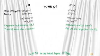
Let's define shear force and bending moments. We combat them using stress matrices. Can someone remind me what shear force does to a cross-section?

It induces shear stress, τ, on the cross-sectional plane.
Spot on! What about bending moments?

That generates normal stress, σ!
Great! Now, let’s move into calculating these stresses using free body diagrams. Do you all recall how to set this up visually?
Calculating Maximum Stress Points
🔒 Unlock Audio Lesson
Sign up and enroll to listen to this audio lesson
Together, we must identify where stress is maximized. Why is knowing the critical cross-section important?
That’s where failure is likely to occur, isn't it?
Right! At the clamped end of our shaft, it's crucial for design safety. Maximum shear stresses need careful evaluation. Anyone want to share how this is usually determined?
We typically compute the principal stresses and use that to identify critical conditions.
Exactly! This analysis shows the limit where our designs need to be strength-oriented.
The Role of Computational Analysis
🔒 Unlock Audio Lesson
Sign up and enroll to listen to this audio lesson
Alright, let's talk about complexities. Why do you think many designs can't be completely analyzed manually?
Because real-world systems are so intricate and can’t be simplified effectively?
Exactly! We need software that can crunch through the variations and manage complex matrices efficiently.
So, simulations can help us predict failure points?
Absolutely! Computational methods become necessary in today's engineering solutions.
Introduction & Overview
Read summaries of the section's main ideas at different levels of detail.
Quick Overview
Standard
Continuing from previous discussions, this section covers the applied forces in a lever design, methods for determining internal stress components due to loads (shear, bending, and torque), and emphasizes the significance of computer analysis in understanding complex stress matrices, especially for materials exhibiting plastic behavior.
Detailed
Theories of Failure (Contd.)
This section elaborates on the theories of failure within solid mechanics, particularly focusing on lever designs that involve applied forces.
Key Points:
- Lever Design: The analysis starts with discussing a lever's design where forces are applied, and how the lever's components (shaft, arm, handle) react under loading conditions.
- Stress Components: The section defines how to analyze shear force (V) and bending moments (M) acting on the shaft. Equations relating these forces are established (e.g., V = F).
- Stress Analysis: Various non-zero stress components (τ, σ) are analyzed through free body diagrams along with illustrations. Stress calculations consider shear force and bending moments acting in different directions.
- Principal Stresses: To determine critical stress points, the principal stress components must be calculated, highlighting the importance of maximum shear stress theory in design. It emphasizes that failure will likely occur at the point experiencing maximum stress.
- Complex Designs: The section concludes by noting that many practical designs involve complexities best handled by computational tools, underscoring the transition from pen-and-paper designs to computer simulations for accurate results.
Youtube Videos


Audio Book
Dive deep into the subject with an immersive audiobook experience.
Designing a Lever
Chapter 1 of 7
🔒 Unlock Audio Chapter
Sign up and enroll to access the full audio experience
Chapter Content
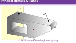
Let us discuss a tougher problem than the one worked out in the previous lecture. Suppose we have to design a lever as shown in Figure 1. The lever has a shaft and an arm. There is also a handle to hold the lever where a force F is applied usually through hands. The other end of the shaft is usually clamped to a machine component.
Detailed Explanation
In this section, we begin by examining the design of a lever, which is a common mechanical device. The lever consists of a shaft that connects to an arm and a handle where a force is applied, typically by hand. It is important to consider that one end of the lever is fixed (clamped) to another machine component while the other end will experience different forces during operation. This understanding is crucial as we will need to ensure that the lever can support the applied forces without failing.
Examples & Analogies
Think of a seesaw at a playground. Children apply force to one side while the other side experiences a force due to their weight. Just like with the lever, the seesaw needs to be designed to handle these forces safely so that it doesn't break or tip over.
Force and Moment Analysis
Chapter 2 of 7
🔒 Unlock Audio Chapter
Sign up and enroll to access the full audio experience
Chapter Content
To design the shaft, we need to find the internal contact force and moment in the shaft’s cross-section. Let us cut a section in the shaft at a distance x from the clamped end and draw the free body diagram of the right part of the shaft as shown in Figure 2.
Detailed Explanation
To analyze the lever's shaft design, we consider the internal forces and moments acting on it. By cutting the shaft at a specific point 'x' from the clamped end, we can create a free body diagram that allows us to visualize these forces. The shear force (V) and bending moment (M) act on the shaft due to the applied force (F). Establishing a balance of these forces and moments is essential to determine whether the shaft can handle the applied loads safely.
Examples & Analogies
Consider a traffic sign held up by a pole. The wind pushes against the sign, creating forces on the pole. By examining where these forces act and how strong they are, engineers can ensure the pole won't topple over, just as we do with the lever shaft.
Stress Components in Cross-Section
Chapter 3 of 7
🔒 Unlock Audio Chapter
Sign up and enroll to access the full audio experience
Chapter Content
We now have to find the stress components generated in the cross-section of the shaft due to these loads. The various non-zero stress components are shown in Figure 3. Due to shear force V, τ acts on the cross-sectional plane.
Detailed Explanation
With the internal forces established, we progress to calculating the stress components in the shaft's cross-section. When the shear force (V) acts along the shaft, it results in shear stresses (τ). Additionally, the bending moment causes normal stresses (σ). Understanding these stress components is vital because they indicate how the material will perform under load, leading us to design the shaft effectively.
Examples & Analogies
Imagine squeezing a sponge from the sides (shearing) and bending it at the same time. The stress experienced on the edges is like the shear stress, while the bend creates a different type of stress, similar to what happens in our lever shaft.
Superposition of Stress Components
Chapter 4 of 7
🔒 Unlock Audio Chapter
Sign up and enroll to access the full audio experience
Chapter Content
The final stress matrix for a general point in the cross-section can be obtained by superposition of all the above stress components. This stress matrix in the cylindrical coordinate system becomes...
Detailed Explanation
To analyze the overall stress state at any point within the cross-section, we use the principle of superposition. This principle allows us to combine the individual effects of different stress components (shear, normal stresses) into a single stress matrix. While this process is mathematical, it forms the foundation for assessing how safe the shaft design is against potential failure.
Examples & Analogies
Imagine layering different colors of paint on a surface. Each layer affects the final color you see. Similarly, different stresses contribute to the overall stress state of the shaft.
Identifying Critical Cross-Section
Chapter 5 of 7
🔒 Unlock Audio Chapter
Sign up and enroll to access the full audio experience
Chapter Content
Thus, the cross-section at the clamped end is the critical cross-section and failure will occur first in this cross-section. We thus focus on this cross-section for our analysis which is also shown in Figure 4.
Detailed Explanation
Through analysis, we've identified that the clamped end of the lever's shaft experiences the highest stresses and is therefore the critical section for failure. Focusing on this specific area enables us to design the shaft to ensure it can withstand the corresponding loads without experiencing failure, directly informing the safety and longevity of our lever system.
Examples & Analogies
Think of a bridge. Engineers focus intensely on the support pillars because that's where the most weight is concentrated. By ensuring those pillars can hold up, the entire structure becomes safer, just like with our shaft analysis.
Calculating Maximum Stresses
Chapter 6 of 7
🔒 Unlock Audio Chapter
Sign up and enroll to access the full audio experience
Chapter Content
For this cross-section, bending stress σ equals ... It is just a function of y and hence it is maximum at the two points shown in Figure 4.
Detailed Explanation
Next, we derive the specific equations for bending stress (σ) and shear stress (τ) based on their positions within the cross-section. Understanding these peak stresses allows us to predict where failure is likely to first occur under operational conditions. This precision is crucial in ensuring safety and functionality in design.
Examples & Analogies
Consider tightening a screw; if you apply too much force, it can strip or break. Knowing how tough a given spot can handle helps avoid failure, just like determining where the maximum stress occurs in our lever lets us design it to last.
Final Thoughts on Stress Analysis
Chapter 7 of 7
🔒 Unlock Audio Chapter
Sign up and enroll to access the full audio experience
Chapter Content
We have thus found that the three stress components τ, τ, and σ attain their maximum values at different points. So, this does not turn out to be an easy problem.
Detailed Explanation
In our analysis of the lever shaft, we discovered that the maximum values of stress components do not occur at the same locations, indicating the complexity involved in stress analysis for mechanical designs. This complexity emphasizes the need for sophisticated computational tools in real-world engineering applications, as manual calculations become impractical.
Examples & Analogies
Think about planning a vacation; each location has its unique attractions, but finding the perfect balance can be complex. Just like, understanding different stresses requires advanced tools to sort through, ensuring design success without risking failure.
Key Concepts
-
Lever Design: Analyzing forces applied to a lever and understanding their effects on internal stresses.
-
Stress Components: Identifying shear and bending stresses acting on the material due to applied loads.
-
Critical Cross-Section: The location where maximum stress occurs and likely points of material failure.
-
Computational Analysis: The necessity of computer-based methods to analyze complex structure designs.
Examples & Applications
In a lever design, applying a force at one end creates shear stress along the shaft. Understanding this helps in determining how much load the shaft can withstand.
When calculating the bending moment on a shaft, knowing the distance from the load application point to the supports allows engineers to calculate the resultant bending stress effectively.
Memory Aids
Interactive tools to help you remember key concepts
Rhymes
In a lever, forces apply, stress and strain, oh my! Bending here and shearing there, safety first, it’s only fair.
Stories
Imagine a lever at a carnival game. As kids pull the handle, the lever bends at different points. Watching those stress points teaches us where to reinforce and keep it safe!
Memory Tools
Forces, Stresses, Moments - remember FSM! This can help you recall key components in lever design.
Acronyms
D.O.C - Design, Observe, Calculate! A short mantra for effective lever analysis.
Flash Cards
Glossary
- Shear Force (V)
A force that acts parallel to the cross-section and induces shear stress.
- Bending Moment (M)
A moment that causes bending of an object, leading to normal stress.
- Maximum Shear Stress Theory
A failure criterion used to determine when material will yield due to shear stress.
- Stress Matrix
A representation of various stress components acting at a point in a material.
- Principal Stress
The maximum or minimum normal stress at a point in a material.
Reference links
Supplementary resources to enhance your learning experience.