
Shear Force and Bending Moment Diagrams
Enroll to start learning
You’ve not yet enrolled in this course. Please enroll for free to listen to audio lessons, classroom podcasts and take practice test.
Interactive Audio Lesson
Listen to a student-teacher conversation explaining the topic in a relatable way.
Static Determinacy Check
🔒 Unlock Audio Lesson
Sign up and enroll to listen to this audio lesson

First, we need to verify if our frame is statically determinate. This means it must have enough equations to solve for all the unknowns. Does anyone know how to check if a structure is statically determinate?

We can use the degree of static indeterminacy formula!
Exactly! The formula is usually stated as the number of reactions + the number of internal forces - the number of equations of equilibrium. If it's zero, it's statically determinate. What happens if it's more than zero?

Then it's statically indeterminate!
Correct! Great start, now let's move to determining support reactions in step 2.
Determining Support Reactions
🔒 Unlock Audio Lesson
Sign up and enroll to listen to this audio lesson

In the next step, we need to calculate the support reactions. We draw a free-body diagram. Can someone explain what a free-body diagram is?

It's a diagram that shows all the forces acting on a structure, right?
Exactly! We represent all external loads and reactions. Once we've done that, we apply equilibrium equations. What are the equilibrium equations?

Sum of vertical forces equals zero, sum of horizontal forces equals zero, and sum of moments equals zero!
Perfect! Let's apply those equations to find the support reactions.
Member End Forces
🔒 Unlock Audio Lesson
Sign up and enroll to listen to this audio lesson
Now that we have our support reactions, the next step is to determine member end forces. How do we start this process?
We should choose a coordinate system for our member, right?
Yes! A common XY coordinate system helps in maintaining clarity. It's important to illustrate internal forces on the free-body diagrams of the joints as well. Who remembers how we should assume the direction of forces?
We assume forces in the positive X and Y directions and counterclockwise moments!
Great! Always remember Newton's third law when determining the direction of forces. Let's compute these forces next.
Constructing Shear and Moment Diagrams
🔒 Unlock Audio Lesson
Sign up and enroll to listen to this audio lesson
We're nearing the end! The next part involves constructing the shear and bending moment diagrams. What is our starting point for this?
We select a local xy coordinate system on each member?
Correct! After setting that up, what do we do next?
We resolve the external loads into components and then determine total axial force and shear for each end?
Exactly right! Drawing these diagrams helps visualize where the forces are acting throughout the member's length. Let’s move on to how to graph these results.
Qualitative Deflected Shape
🔒 Unlock Audio Lesson
Sign up and enroll to listen to this audio lesson
Lastly, we will draw the qualitative deflected shape of our frame based on the bending moment diagram. What's important to remember about how we sketch this?
We have to connect the individual deflected shapes of each member?
Yes! And we must maintain original angles at the joints while neglecting shear and axial deformations. Can someone summarize what the bending moment diagram shows us?
It shows the moments acting on the compression sides of members.
Great summary! Understanding how the frame deforms is fundamental in analyzing structural behavior.
Introduction & Overview
Read summaries of the section's main ideas at different levels of detail.
Quick Overview
Standard
The section outlines a step-by-step approach to analyzing shear force and bending moment diagrams in statically determinate structures, including determining support reactions, member forces, and constructing the diagrams systematically while employing free-body diagrams.
Detailed
Shear Force and Bending Moment Diagrams
Overview
This section covers the methodology for analyzing shear force and bending moment diagrams in plane statically determinate frames, emphasizing the necessity of clear organization in force analysis.
Procedure for Analysis
The analysis can be broken down into several essential steps:
- Static Determinacy Check: Determine if the frame is statically determinate and stable.
- Support Reactions: Create a free-body diagram and compute support reactions using equilibrium equations. This outlines the forces acting on the structure.
- Member End Forces: Define directions for internal forces at the ends of the member following a global coordinate system. Draw free-body diagrams representing various forces acting on the joints and members, adhering to equilibrium principles.
- Shear, Bending Moment, and Axial Force Diagrams: Construct diagrams for shear, bending moments, and axial forces by selecting a local coordinate system for each member and resolving forces.
- Deflected Shape Representation: Using the bending moment diagrams created, sketch a qualitative deflected shape for the frame to visualize deformations.
Each step involves careful documentation of forces, moments, and the application of Newton's laws, which are crucial for accurately assessing structural behavior under various loading conditions.
Youtube Videos


Audio Book
Dive deep into the subject with an immersive audiobook experience.
Procedure for Analysis Overview
Chapter 1 of 6
🔒 Unlock Audio Chapter
Sign up and enroll to access the full audio experience
Chapter Content
The following step-by-step procedure can be used for determining the member end forces as well as the shears, bending moments, and axial forces in members of plane statically determinate frames:
Detailed Explanation
This section outlines a systematic approach to analyze statically determinate frames, which are structures where the internal forces and reactions can be determined using only the equations of equilibrium. The analysis consists of several steps that must be followed in order to achieve accurate calculations of forces and moments within the structure.
Examples & Analogies
Think of analyzing a statically determinate frame like assembling a puzzle. Each piece (frame member) must fit together without conflict (ensuring equilibrium) to complete a picture (the overall force distribution). If one piece is wrong, the entire picture becomes distorted.
Static Determinacy Check
Chapter 2 of 6
🔒 Unlock Audio Chapter
Sign up and enroll to access the full audio experience
Chapter Content
- Check for static determinacy. Using the procedure described in the preceding section, determine whether or not the given frame is statically determinate. If the frame is found to be statically determinate and stable, proceed to step 2. Otherwise, end the analysis at this stage.
Detailed Explanation
The first step is to confirm whether the frame can be analyzed using static equilibrium. A statically determinate frame allows the calculation of internal forces using only external forces and reactions. If the frame is not statically determinate, it needs additional analysis methods—not covered in this procedure.
Examples & Analogies
Imagine trying to balance a seesaw; if it's too heavy on one side (indicating instability), it won't be statically determinate. You can't analyze it properly until it's balanced.
Determining Support Reactions
Chapter 3 of 6
🔒 Unlock Audio Chapter
Sign up and enroll to access the full audio experience
Chapter Content
- Determine the support reactions. Draw a free-body diagram of the entire frame, and determine reactions by applying the equations of equilibrium and any equations of condition that can be written in terms of external reactions only.
Detailed Explanation
The next step involves creating a free-body diagram (FBD) which visually represents the structure and its external forces. By applying the equations of equilibrium (sum of forces in any direction equals zero), you can find the support reactions at fixed supports and roller joints. If the frame is internally unstable, not all reactions may be calculable.
Examples & Analogies
Consider a bridge supported at both ends; understanding how much weight it can hold at its center (how much reaction force each support needs to provide) is like creating an FBD. You sketch it to visualize where forces act and solve for unknowns.
Member End Forces Calculation
Chapter 4 of 6
🔒 Unlock Audio Chapter
Sign up and enroll to access the full audio experience
Chapter Content
- Determine member end forces. It is usually convenient to specify the directions of the unknown forces at the ends of the members of the frame by using a common structural (or global) XY coordinate system...
Detailed Explanation
In this step, you establish a coordinate system to analyze forces at each member's ends. By drawing free-body diagrams for each member, you can identify internal forces and moments. Assumptions about force directions can be made for calculation purposes, but adjustments will be necessary to respect Newton's third law when assessing opposing forces.
Examples & Analogies
Think of a tug-of-war: each end of the rope experiences forces that must be understood in terms of direction. If one team pulls left (one end’s force), the opposing team’s pull creates tension (the other end’s reaction), which is akin to calculating member forces in a frame.
Shear and Bending Moment Diagrams
Chapter 5 of 6
🔒 Unlock Audio Chapter
Sign up and enroll to access the full audio experience
Chapter Content
- For each member of the frame, construct the shear, bending moment, and axial force diagrams as follows...
Detailed Explanation
Once the member end forces are known, you can draw shear force, bending moment, and axial force diagrams. These diagrams visually represent how forces change along the length of each member. The shear diagram indicates how forces vary between the member's ends, while the bending moment diagram shows how moments apply along the length.
Examples & Analogies
Think of a swimming pool's water surface in response to waves: at different points in the pool, the height varies (shear) and the force that causes the water to push up or down varies (bending). Placing forces and moments accurately illustrates how materials will react under load.
Qualitative Deflected Shape
Chapter 6 of 6
🔒 Unlock Audio Chapter
Sign up and enroll to access the full audio experience
Chapter Content
- Draw a qualitative deflected shape of the frame. Using the bending moment diagrams constructed in step 4, draw a qualitative deflected shape for each member of the frame...
Detailed Explanation
This final step involves visually approximating how the structure will deform under the loads applied. You'll connect deflected shapes of individual members at the joints, ensuring the structure’s angles and supports are maintained. Although bending and shear are shown, axial deformations are usually negligible and often disregarded.
Examples & Analogies
Visualize how a trampoline deforms when you jump—while it bends in the middle (bending moments), its stretch in length (axial forces) is minimal. Similarly, the deflected shape of a structure illustrates the impact of applied forces.
Key Concepts
-
Static Determinacy: A structural condition allowing for the application of equilibrium principles.
-
Free-body Diagram: A crucial tool for visualizing the forces acting on a structure.
-
Equilibrium Equations: Essential for solving for unknown supports in structures.
-
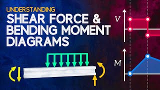
Shear Force Diagram: Illustrates how shear forces vary along a member.
-
Bending Moment Diagram: Represents internal moments and influences deflection behavior.
Examples & Applications
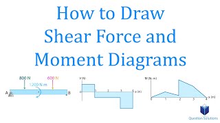
Example 1: Analyzing a cantilever beam with a point load and constructing its shear and moment diagrams.
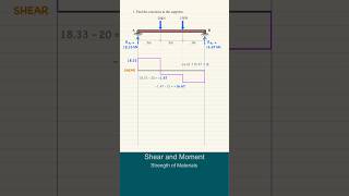
Example 2: A two-span continuous beam under uniform loading, illustrating shear and bending moment distribution.
Memory Aids
Interactive tools to help you remember key concepts
Rhymes
Shear forces slice, moments bend, with free-body diagrams, our truths we send.
Stories
Once upon a time, a structure woke up to find itself floating between two supports. It had friends applying loads from above and below. To understand their impact, it drew a picture—a free-body diagram, revealing the forces acting on it and defining its destiny.
Memory Tools
MEMES - Moments, Equilibrium, Member End forces, Shear forces. Remember to consider all these when analyzing frames!
Acronyms
SHEAR - Support reactions, Hinge moments, Equilibrium equations, Axial forces, Resultant forces.
Flash Cards
Glossary
- Shear Force
The internal force acting parallel to the cross-section of a structural member.
- Bending Moment
The internal moment that causes a member to bend due to external loads.
- Freebody Diagram
A diagram that shows all the forces and moments acting on a structure or part of a structure.
- Static Determinacy
A structural condition where a structure has enough support and constraints to allow for equilibrium.
- Equilibrium Equations
Mathematical expressions that represent the balance of forces and moments acting on a system.
- Axial Force
The component of a force that acts along the length of a structural member.
Reference links
Supplementary resources to enhance your learning experience.