
Review from Strength of Materials
Enroll to start learning
You’ve not yet enrolled in this course. Please enroll for free to listen to audio lessons, classroom podcasts and take practice test.
Interactive Audio Lesson
Listen to a student-teacher conversation explaining the topic in a relatable way.
Flexure of Beams
🔒 Unlock Audio Lesson
Sign up and enroll to listen to this audio lesson

Today, we are focusing on the behavior of beams subjected to bending. Can anyone tell me what happens when a straight beam is bent?

It changes shape, right? Does it remain straight?
Exactly! It deforms but maintains the normal plane cross-sections. This principle is crucial in understanding beam mechanics. When we apply a bending moment, like end couples, we create a curved shape. Does that make sense?

Yes, the bending causes the sections to move further from the neutral axis.
Good point! Let’s remember this with the mnemonic 'Bend Like a Bow,' which emphasizes that bending alters the bowing shape of the beam.

What about stress in this bending?
Great question! Stress varies across the cross-section. The strain is proportional to the distance from the neutral axis, represented mathematically. Can someone tell me what the bending moment equation is?

It’s M = ∫y dA, right?
Exactly! This equation helps us calculate moments based on stress distribution. Remember, this is foundational for understanding beam design.
To summarize, when we bend a beam, we maintain the planeness of sections, and we determine stress and moments using the defined relationships. Keep 'Bend Like a Bow' in mind when thinking about beam flexure!
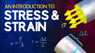
Stress-Strain Relationship
🔒 Unlock Audio Lesson
Sign up and enroll to listen to this audio lesson

Now, let’s discuss the stress-strain relationship in more detail. What do you think happens to materials under stretching or bending?
They stretch and become thinner, I think?
Yes! Stress increases as we move away from the neutral axis. At the neutral axis, the stress is zero. Can anyone explain why we care about this in design?
It helps us determine the material’s ability to support loads?
Correct! We can use stress-strain diagrams, rotated 90 degrees, to visualize this. The relationship tells us how materials will behave and help us design safely.
Are there variations in this stress for different shapes?
Absolutely! Different cross-sections have unique stress distributions. Remember to analyze shapes like W sections carefully, as they carry shear differently. A classic rhyme for this concept is ‘Shape defines fate,’ which reinforces the importance of cross-sectional design.
To summarize this session, understanding the stress-strain relationship is vital for predicting material behavior under bending loads.
Nominal Strength
🔒 Unlock Audio Lesson
Sign up and enroll to listen to this audio lesson
Let’s shift focus to nominal strength. Who can remind us of the importance of the strength reduction factor?
Isn’t it to ensure safety in designs and account for uncertainties?
Right! In LRFD, we use a strength reduction factor of 0.90 for flexure. Can someone share the equation we use to express this?
It’s N = φM_n, where φ is the reduction factor and M_n is the nominal moment strength.
Exactly! And there's a distinction between compact and partially compact sections. Why do we need to classify them?
To know what type of analysis to apply during design, right?
Yes! Understanding these classifications helps us predict failure modes such as local buckling. Remember the acronym 'SPACe': Section, Properties, Analysis, Classification, to keep these concepts organized!
So, summarizing today's discussion: the reduction factor is key for safe designs, with classification ensuring correct analysis and strength evaluation.
Introduction & Overview
Read summaries of the section's main ideas at different levels of detail.
Quick Overview
Standard
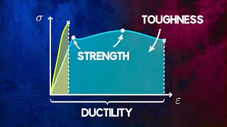
In this section, the fundamental principles of flexural behavior, stress and strain relationships in beams, and the factors governing beam strength are explored, emphasizing the significance in structural engineering design.
Detailed
Review from Strength of Materials
This section delves into the principles of flexure, detailing how originally straight beams behave when subjected to bending forces. The key concepts include:
- Flexural Behavior: Understanding how beams bend and maintain plane cross-sections normal to the beam's length.
- Stress-Strain Relationship: The variation of stress across a beam's cross-section is governed by the stress-strain diagram, seen as a relationship between strain and the distance from the neutral axis.
- Bending Moment Equation: The equation for bending moment, derived from the distribution of stress over the beam's area, indicates how bending moments can be calculated using the formula M = ∫y dA.
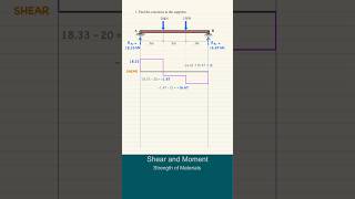
- Shear Formula: The relationship of shear in the beam illustrated by the equation Q = ∫y dA can be critical in determining shear forces within structural components, especially for different shapes like rectangular beams.
- Nominal Strength: The section further explains the nominal moments for different sections with guidelines on strength reduction factors essential for load and resistance factor design (LRFD).
- Failure Modes: An exploration of limit states for steel beams, including local buckling due to various loading conditions.
Youtube Videos


Audio Book
Dive deep into the subject with an immersive audiobook experience.
Flexure of Beams
Chapter 1 of 4
🔒 Unlock Audio Chapter
Sign up and enroll to access the full audio experience
Chapter Content
Fig.20.1 shows portion of an originally straight beam which has been bent to the radius (cid:26) by end couples M, thus the segment is subjected to pure bending. It is assumed that plane cross-sections normal to the length of the unbent beam remain plane after the beam is bent.
Detailed Explanation
When a beam is subjected to bending, it assumes a curved shape rather than staying straight. In this situation, we assume that cross-sections of the beam that are perpendicular to its length (the way the beam originally was before bending) still remain flat and unaltered after bending, which is a crucial assumption in beam theory known as the plane sections remain plane assumption. This simplification allows for easier calculations and helps in understanding how beams behave under loads.
Examples & Analogies
Think about bending a flexible straw. If you bend one part of the straw, the parts upstream and downstream of the bend don't curve – they stay straight. Similarly, when we analyze a beam, we assume that these sections do not deform in a complex way during the bending process.
Strain in Beams
Chapter 2 of 4
🔒 Unlock Audio Chapter
Sign up and enroll to access the full audio experience
Chapter Content
Therefore, considering the cross-sections AB and CD a unit distance apart, the similar sectors Oab and bcd give y = (cid:26) where y is measured from the axis of rotation (neutral axis). Thus strains are proportional to the distance from the neutral axis.
Detailed Explanation
In a bent beam, there's a crucial line called the neutral axis, which is the line where material experiences no tension or compression. Above this axis, the material will be under compression, while below it, the material is under tension. The distance from this neutral axis, represented as 'y,' determines how much strain (deformation) occurs. The further from the neutral axis you are, the more strain you experience; this relationship helps us understand how stresses vary throughout the beam’s cross-section.
Examples & Analogies
Imagine holding a rubber band tightly and slowly bending it. The inner side of the bend (closest to the center) gets compressed, while the outer side (furthest from the center) stretches. The same principle applies to beams: the distance from the neutral axis dictates whether the material is being squished or pulled.
Stress Distribution
Chapter 3 of 4
🔒 Unlock Audio Chapter
Sign up and enroll to access the full audio experience
Chapter Content
The corresponding variation in stress over the cross-section is given by the stress-strain diagram of the material rotated 90o from the conventional orientation, provided the strain axis is scaled with the distance y. The bending moment M is given by M = y(cid:27)dA (20.2) where dA is a differential area a distance y from the neutral axis.
Detailed Explanation
The distribution of stress throughout the beam’s cross-section is related to the bending moment applied. This stress varies linearly with distance from the neutral axis. The bending moment, which is a measure of the bending effect due to forces acting on the beam, can be calculated using the equation M = y*dA, where dA is an infinitesimally small area at a distance y from the neutral axis. This relationship is essential for determining how much load the beam can handle and where the stresses are concentrated.
Examples & Analogies
Consider a seesaw; the further you sit from the pivot point, the more moment (or 'bending effect') your weight exerts on the seesaw. Likewise, in a beam, points further away from the neutral axis create more stress and influence the overall strength and reliability of the beam.
Understanding Shear Stresses
Chapter 4 of 4
🔒 Unlock Audio Chapter
Sign up and enroll to access the full audio experience
Chapter Content
For a rectangular beam, we will have a parabolic shear stress distribution. For a W section, it can be easily shown that about 95% of the shear force is carried by the web, and that the average shear stress is within 10% of the actual maximum shear stress.
Detailed Explanation
The distribution of shear stress in a beam is not uniform. For a rectangular beam, the shear stress distribution has a parabolic shape, meaning it is maximum at the center and decreases toward the edges. For more complex shapes like W sections (wide flange beams), most of the shear force is supported by the web (the vertical part of the beam), which is critical for understanding how different beams respond to loads. Recognizing how shear stress behaves helps engineers design safer and more efficient structures.
Examples & Analogies
Think of a sponge soaked in water. When you squeeze it, the water (representing shear force) is most concentrated in the middle, and as you move toward the edges, it becomes less. This analogy helps visualize how shear stresses concentrate within a beam.
Key Concepts
-
Flexural Behavior: The way beams deform under bending loads.
-
Bending Moment: The internal force causing bending articulated through the equation M = ∫y dA.
-
Neutral Axis: The point along the beam where no stress is experienced.
Examples & Applications
Example of a simply supported beam under a central load illustrating flexural behavior.
Applying the bending moment equation to calculate stress across a W-section beam.
Memory Aids
Interactive tools to help you remember key concepts
Rhymes
Bend Like a Bow; it shapes as it goes.
Stories
Imagine a bow bending under pressure; where it buckles, it bears the weight.
Memory Tools
SPACe for Section properties, Analysis, and Classification in design.
Acronyms
FLEX for Flexural behavior as Loads eXercise beams.
Flash Cards
Glossary
- Flexure
The bending of a beam when subjected to external loads.
- Neutral Axis
The line along a beam's length where the material experiences zero stress during bending.
- Bending Moment
The internal moment that induces bending of a structural element.
- StressStrain Diagram
A graphical representation of the relationship between stress and strain for a material.
- Nominal Strength
The calculated strength of a member under specified loading conditions.
- Strength Reduction Factor
A factor used in design calculations to account for uncertainties in material strength or loading.
Reference links
Supplementary resources to enhance your learning experience.