
Introduction
Enroll to start learning
You’ve not yet enrolled in this course. Please enroll for free to listen to audio lessons, classroom podcasts and take practice test.
Interactive Audio Lesson
Listen to a student-teacher conversation explaining the topic in a relatable way.
Beam-Column Connections Overview
🔒 Unlock Audio Lesson
Sign up and enroll to listen to this audio lesson

Today, we will discuss beam-column connections, a fundamental concept in structural engineering. Does anyone know what a beam-column connection is?

Is it just where the beam meets the column?
Exactly! It's where these two elements join and transfer loads between each other. Now, can anyone tell me the three types of beam-column connections?

Flexible, rigid, and semi-rigid?
Correct! Let’s dive deeper into each type starting with flexible connections. These are like hinges that only transfer forces but not moments. Can anyone explain why that might be important?

Because it simplifies the calculation for loads?
Exactly! And what about rigid connections?

They transfer both forces and moments, meaning they keep stability in the structure.
Great observation! Let’s summarize: beam-column connections are critical for load transfer, with flexibility allowing only force transfer and rigidity allowing both forces and moments. Remember this with the acronym 'F.R.S.' for Flexible, Rigid, and Semi-Rigid.
Behavior of Simple Frames
🔒 Unlock Audio Lesson
Sign up and enroll to listen to this audio lesson

Now let’s explore how simple frames behave under vertical loads. Who can tell me what happens when a rigid connection is applied in a frame?
It reduces the maximum moment in the beam.
Correct! And what is the trade-off?
Negative moments at the ends of the beams?
Exactly! That's crucial because these negative moments could complicate design considerations. Can anyone think of a real-world situation where this might apply?
Maybe in tall buildings where wind forces are a factor?
Right! Understanding these effects helps in designing for stability and safety. Let’s summarize—rigid connections minimize moments but introduce negative moments at the ends, which we need to account for.
Recap and Application
🔒 Unlock Audio Lesson
Sign up and enroll to listen to this audio lesson
As we close today, let’s recap the types of beam-column connections. Can anyone name them and give a brief description?
Flexible allows force transfer only, rigid allows both forces and moments, and semi-rigid does some of each!
Perfect! Now, if we were to design a new building, what types of connections might we consider based on what we've learned?
Maybe rigid connections for areas where stability is a concern, like higher floors, and flexible connections where loads are less critical?
Excellent strategy! It’s important to consider context in design. Allow me to introduce a mnemonic: 'R.F.S. for Rigid, Flexible, Semi-Rigid' which can help you remember these types.
Thanks! That will make it easier to recall.
Great! Remember, understanding beam-column connections is essential for maintaining the integrity of structures. Well done today!
Introduction & Overview
Read summaries of the section's main ideas at different levels of detail.
Quick Overview
Standard
The introduction provides an overview of beam-column connections, categorizing them into flexible, rigid, and semi-rigid types. It touches on the significance of these connections in maintaining structural integrity and transferring loads, paving the way for a deeper understanding of frame behavior.
Detailed
Introduction
This section serves as an entry point into the understanding of building structures, specifically focusing on the connection mechanics between beams and columns.
Beam Column Connections
Beam-column connections are crucial in structural engineering as they determine how loads are transferred between beams and columns. There are three main types of connections:
- Flexible Connections: Also known as hinge connections, allow only for force transfer without any moment transfer. The end moments in flexible connections equal zero.
- Rigid Connections: These connections allow for both moment and force transfer, meaning they provide complete rotational continuity between the beam and column, making the moments and rotations at both ends equal.
- Semi-Rigid Connections: This type allows for some moment transfer but not complete. End moments are equal but not zero, which introduces a differential rotation that is resisted by a spring-related force.
Behavior of Simple Frames
The behavior of simple frames under vertical loads indicates that rigid connections can effectively reduce maximum moments in beams. However, this leads to negative moments at the ends that must be considered. Understanding how these connections work and their impacts on overall structural integrity is vital for engineers designing buildings.
Youtube Videos
![27 y/o structural engineer building a learning platform. introduction to structural basics. [ep. #1]](https://img.youtube.com/vi/fZE_OqHS4lY/mqdefault.jpg)


Audio Book
Dive deep into the subject with an immersive audiobook experience.
Connections Between Beams and Columns
Chapter 1 of 4
🔒 Unlock Audio Chapter
Sign up and enroll to access the full audio experience
Chapter Content
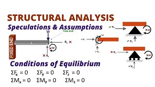
The connection between the beam and the column can be, Fig. 33.1:
1
q b q b q b
q
q q c
c c
q b = q c q b = q c
M= sK s(q b- q c)
q b = q c
Detailed Explanation
The introduction provides a basic overview of how beams and columns connect in building structures. The equations illustrate the relation of forces (q) at these connection points and how moments (M) are defined based on the difference in these forces, indicating different types of connections.
Examples & Analogies
Think of a beam-column connection like a socket and plug. In a flexible connection (the plug), it fits in but can pivot, moving independently without transferring rotational force. In a rigid connection (like a well-fitted plug), it allows no movement and transmits both force and rotational energy. A semi-rigid fit behaves like a slightly loose plug, transferring some degree of electrical energy while moving a bit.
Flexible Connections
Chapter 2 of 4
🔒 Unlock Audio Chapter
Sign up and enroll to access the full audio experience
Chapter Content
Flexible: that is a hinge which can transfer forces only. In this case we really have cantilever action only. In a flexible connection the column and beam end moments are both equal to zero, M = M = 0. The end rotations are not equal, (cid:18) = (cid:18).
Detailed Explanation
Flexible connections act like a hinge, allowing beams and columns to pivot relative to one another. In such connections, the moments at the ends are equal to zero, meaning the forces are transferred without creating any rotational stress. This situation typically occurs in cantilever structures where only one end is fixed.
Examples & Analogies
Imagine a swing with one end attached to a tree branch; it can sway back and forth without any tension at the connection point. The swings move around freely, much like how the beam rotates around the column in a flexible connection.
Rigid Connections
Chapter 3 of 4
🔒 Unlock Audio Chapter
Sign up and enroll to access the full audio experience
Chapter Content
Rigid: The connection is such that (cid:18) = (cid:18) and moment can be transmitted through the beam col connection. In a rigid connection, the end moments and rotations are equal (unless there is an externally applied moment at the node), M = M = 0, (cid:18) = (cid:18).
Detailed Explanation
In rigid connections, both the moments and rotations of connected beams and columns are equal. This means the structure can effectively distribute forces throughout, enhancing stability. In scenarios with external load, such as wind or weight, the rigidity of these connections helps maintain the structure's integrity.
Examples & Analogies
Think of a table where the legs (columns) are firmly attached to the tabletop (beam). If you tilt the table or push down on it, the legs will not move independently; they will all shift in unison, just as rigid connections maintain the same angle during load changes.
Semi-Rigid Connections
Chapter 4 of 4
🔒 Unlock Audio Chapter
Sign up and enroll to access the full audio experience
Chapter Content
Semi-Rigid: The end moments are equal and not equal to zero, but the rotation are different. (cid:18) = (cid:18), M = M = 0. Furthermore, the difference in rotation is resisted by the spring M = K ((cid:18) (cid:18)).
Detailed Explanation
Semi-rigid connections allow some flexibility in beam and column interactions. The end moments may still be equal but are not zero, indicating that while there is some rotational difference, it’s resisted by spring-like forces, allowing for a balance that accommodates minor shifts during load changes.
Examples & Analogies
Think of a car suspension system. The suspension allows the car body and wheel to move at different angles when driving over bumps. The connection between the wheel and the car frame can ideally be dynamic, supporting varying movements yet keeping the alignment in check, similar to how semi-rigid connections allow for some rotation while resisting excessive movement.
Key Concepts
-
Beam-Column Connections: Junctions that support load transfer.
-
Flexible Connection: Transfers forces without moments.
-
Rigid Connection: Transfers both forces and moments for stability.
-
Semi-Rigid Connection: Handles some moment transfer, with equal but not zero end moments.
Examples & Applications
Example of a flexible connection can be seen in residential buildings where walls act as hinges.
In skyscrapers, rigid connections are crucial at level floors to withstand lateral forces.
Memory Aids
Interactive tools to help you remember key concepts
Rhymes
Rigid connections hold tight, keeping structures upright!
Stories
Imagine a dancer using a flexible pole. In each leap, the pole bends but doesn't break, just like a flexible connection in a building!
Memory Tools
Remember the acronym F.R.S. for Flexible, Rigid, Semi-Rigid connections.
Acronyms
FRS stands for Flexible, Rigid, and Semi-Rigid to categorize the connections.
Flash Cards
Glossary
- BeamColumn Connection
The junction where beams and columns meet, crucial for load transfer in structural engineering.
- Flexible Connection
A connection that allows for forces to transfer but not moments, functioning like a hinge.
- Rigid Connection
A connection that transmits both forces and moments, ensuring rotational continuity between connected elements.
- SemiRigid Connection
A connection that allows for some moment transfer but not completely, resulting in equal but non-zero end moments.
- Load Transfer
The method by which loads are directed to support structures.
- Negative Moment
A moment that tends to cause bending in the opposite direction to the applied load.
Reference links
Supplementary resources to enhance your learning experience.