
Equipotential Lines and Phreatic Surface
Enroll to start learning
You’ve not yet enrolled in this course. Please enroll for free to listen to audio lessons, classroom podcasts and take practice test.
Interactive Audio Lesson
Listen to a student-teacher conversation explaining the topic in a relatable way.
Introduction to Flow Nets
🔒 Unlock Audio Lesson
Sign up and enroll to listen to this audio lesson

Welcome class! Today, we are delving into flow nets. Can anyone tell me what flow nets help us visualize?

I think they show how water flows through soil?
Exactly! Flow nets illustrate the movement of groundwater and are essential for understanding hydraulic gradients. Remember the acronym ‘FLOW’ – F for Flow lines, L for Lines of equal potential, O for Understanding how water moves, W for Water levels.

How do we actually draw these flow nets?
Great question! We start by marking the boundary conditions and making a rough sketch first. Let's go over that process step by step.

What's the first thing we should do?
The first step is marking all boundary conditions. Always remember: boundaries are key to knowing how to shape your flow lines!

What about the lines themselves?
We can think of them as two sets: equipotential lines that represent points of equal head, and flow lines showing the direction of flow. Visualizing this correctly is crucial!
To wrap this up, remember – flow nets help visualize groundwater movement, and boundary conditions are the first step in crafting them.
Construction of Flow Nets
🔒 Unlock Audio Lesson
Sign up and enroll to listen to this audio lesson

Let’s dive into the construction process. After we sketch our boundary conditions, what do we do next?
We draw a coarse net with flow lines first?
Correct! It's easier to understand the pattern of water flow first with flow lines. After that, we adjust the mesh to have square fields between the lines. Why do we want squares?
So that the head loss is consistent between lines?
Exactly! We ensure a uniform head loss, which is crucial for accurate representation. We then refine the net by repeating this step until we get a nice clean net.
What if the flow isn’t uniform?
Good observation! Adjustments may be necessary to respond to different flow conditions. Consistency in your adjustments is key.
In summary, start with a coarse net, adjust for squares, and refine until it matches all conditions. That’s your pathway to a successful flow net!
Boundary Conditions in Flow Nets
🔒 Unlock Audio Lesson
Sign up and enroll to listen to this audio lesson
Now let's discuss boundary conditions. Can anyone remind me what a submerged permeable soil boundary signifies in a flow net?
It's an equipotential line, right?
Exactly! When drawing flow nets, any submerged permeable boundary behaves as an equipotential line. Can you think of why that is?
Because the water level would be the same at all points along it?
That’s correct! Now, how about the boundary between permeable and impermeable soils – what does that represent?
It’s a flow line because that's where the water cannot pass.
You're catching on quickly! This boundary is critical for understanding water movement. Remember this as you visualize groundwater flow!
Practical Applications of Flow Nets
🔒 Unlock Audio Lesson
Sign up and enroll to listen to this audio lesson
Now, let’s talk about how understanding flow nets can benefit us in real-world scenarios. What can proper flow net drawings help us with?
They would help manage groundwater resources and prevent flooding.
Exactly! They are vital in environmental engineering and construction. Who can give me an example of where this knowledge is applied?
In designing drainage systems, right?
Yes! Proper drainage design ensures we control water flow and prevent soil erosion. Remember: Flow nets = groundwater management!
Introduction & Overview
Read summaries of the section's main ideas at different levels of detail.
Quick Overview
Standard
The section outlines the process of creating flow nets by trial and error, detailing how equipotential lines, flow lines, and boundary conditions can be identified and represented. Understanding these concepts is crucial for visualizing the flow of water through soil and determining hydraulic gradients.
Detailed
Equipotential Lines and Phreatic Surface
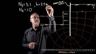
This section explores the methodology for constructing flow nets in the study of groundwater flow through soils. At any point (x,z) in the soil, there exists a value of hydraulic head, represented by h(x,z). By drawing contours of equal head, or equipotential lines, one can visualize the hydraulic gradient.
The construction of flow nets follows a systematic approach:
1. Boundary Conditions: The first step involves marking all relevant boundary conditions and sketching a flow cross-section to scale.
2. Initial Net: A coarse grid is drawn with orthogonal equipotential and flow lines. It's often more intuitive to draw the flow lines first, as they represent the direction of water movement.
3. Mesh Adjustment: The mesh is modified to ensure adjacent flow and equipotential lines maintain square sub-regions, ensuring consistency in hydraulic head loss (∆h) between lines.
4. Refinement: The net is refined repeatedly until it meets all conditions outlined above.
Key boundary conditions include:
- Submerged Boundaries: Where a permeable soil boundary exists, it acts as an equipotential line, with equal water levels across imaginary standpipes.
- Permeable vs. Impermeable: The transition between permeable and impermeable soil is marked by flow lines.
- Phreatic Surface: Equipotential lines intersecting the phreatic surface create points at equal vertical intervals, which are essential for understanding groundwater movement.
This detailed exploration of flow nets not only aids in visualizing groundwater flow but also prepares students for practical applications in hydrogeological studies.
Youtube Videos


Audio Book
Dive deep into the subject with an immersive audiobook experience.
Definition of Equipotential Lines
Chapter 1 of 4
🔒 Unlock Audio Chapter
Sign up and enroll to access the full audio experience
Chapter Content
At every point (x,z) where there is flow, there will be a value of head h(x,z). In order to represent these values, contours of equal head are drawn.
Detailed Explanation
Equipotential lines are special lines in a fluid flow situation where the potential energy is the same at every point along the line. Specifically, at any point defined by coordinates (x, z), the fluid's pressure or energy level (referred to as 'head') is equal. This means that there is no flow across an equipotential line; flow only occurs parallel to the lines.
Examples & Analogies
Imagine a hilly landscape where water flows downhill. The lines drawn at the same height above sea level represent equipotential lines. No matter where you measure in that specific line, the height is the same, indicating that water has potential energy at that level but isn’t moving across these lines.
Flow Nets and Construction Process
Chapter 2 of 4
🔒 Unlock Audio Chapter
Sign up and enroll to access the full audio experience
Chapter Content
A flow net is to be drawn by trial and error. For a given set of boundary conditions, the flow net will remain the same even if the direction of flow is reversed. Flow nets are constructed such that the head lost between successive equipotential lines is the same, say ∆h.
Detailed Explanation
Flow nets help visualize the flow of water through soil by drawing both flow lines and equipotential lines. The construction process is iterative—meaning you start with a basic design and refine it repeatedly. You want to ensure that the loss of head (energy loss) between the equipotential lines is consistent (denoted as ∆h) and that the lines are perpendicular (orthogonal) to each other, defining the grid of the net.
Examples & Analogies
Think of it like laying a grid over the water surface in a pond. Initially, you randomly place some lines, but as you observe how the water flows under different conditions, you adjust the grid until the lines perfectly show the flow direction. Each adjustment teaches you something about where the water flows and how deeply it can have energy.
Boundary Conditions for Flow Nets
Chapter 3 of 4
🔒 Unlock Audio Chapter
Sign up and enroll to access the full audio experience
Chapter Content
The most common boundary conditions are: (a) A submerged permeable soil boundary is an equipotential line. (b) The boundary between permeable and impermeable soil materials is a flow line.
Detailed Explanation
Boundary conditions are key to creating accurate flow nets. An example of a boundary condition is a submerged soil boundary, which acts like an equipotential line where water levels remain constant. Conversely, at the junction of permeable and impermeable materials, the behavior of the flow changes, creating a flow line where water can either enter or not, reflecting how water interacts with different materials.
Examples & Analogies
Picture a sponge (permeable) resting on a flat surface (impermeable). The surface might hold water, but the sponge allows water to flow through it while the bottom remains dry. When drawing the flow net, you would represent the sponge's surface as equipotential while the flat surface serves as a boundary line where flow is defined.
Equipotential Lines and Phreatic Surface Relationship
Chapter 4 of 4
🔒 Unlock Audio Chapter
Sign up and enroll to access the full audio experience
Chapter Content
Equipotential lines intersecting a phreatic surface do so at equal vertical intervals.
Detailed Explanation
The phreatic surface is the upper surface of the groundwater in an unconfined aquifer. It intersects equipotential lines at equal vertical intervals, signifying how groundwater levels stabilize across the landscape. This consistent spacing helps scientists and engineers understand how groundwater flows and how it is influenced by surface features.
Examples & Analogies
Consider a large sponge soaking in water. The water represents the phreatic surface. Just like the water level in the sponge rises evenly at different points, creating a level saturation across the sponge, the equipotential lines intersect the phreatic surface not in random patterns, but consistently, demonstrating a balance in pressure throughout.
Key Concepts
-
Flow Nets: Visual tools used to understand groundwater movement.
-
Equipotential Lines: Illustrate zones of equal hydraulic head.
-
Flow Lines: Indicate the direction of groundwater flow.
-
Phreatic Surface: The boundary above which soils are unsaturated.
-
Boundary Conditions: Define how flow is influenced at specific limits.
Examples & Applications
Example 1: Constructing a flow net for a drainage basin to visualize groundwater movement and identify potential flooding areas.
Example 2: Using equipotential lines to assess water table levels and determine the impact of construction on local groundwater flow.
Memory Aids
Interactive tools to help you remember key concepts
Rhymes
Equipotential lines, heads align, at equal heights they intertwine.
Stories
Imagine a hero, Waterman, who can only flow along pathways marked by head. These pathways are his equipotential lines that guide him safely through the soil.
Memory Tools
Remember 'FLOWS' - F for Flow lines, L for Lines of equal potential, O for Observing water levels, W for Water movement, S for Submerged boundaries.
Acronyms
Use 'B-FLOW' to remember vital aspects
for Boundary conditions
for Flow lines
for levels
for observing
for water gradients.
Flash Cards
Glossary
- Equipotential Lines
Lines that represent points of equal hydraulic head in a given setting.
- Flow Lines
Lines that indicate the direction of groundwater flow, tangential to the flow at any point.
- Phreatic Surface
The upper surface of groundwater in an unconfined aquifer, above which soil pores are not saturated.
- Boundary Conditions
Specific predetermined conditions that affect the flow within defined limits.
- Hydraulic Head
The total potential energy of water in a system, often measured in terms of height.
Reference links
Supplementary resources to enhance your learning experience.