
Sources of Signal Integrity Issues
Interactive Audio Lesson
Listen to a student-teacher conversation explaining the topic in a relatable way.
Transmission Line Effects
🔒 Unlock Audio Lesson
Sign up and enroll to listen to this audio lesson

Today, we're going to talk about transmission line effects. Who can explain what happens when a signal travels along a trace on a PCB?

Is it true that if the trace is too long, it behaves like a transmission line?
Absolutely, Student_1! When the length of the trace is comparable to the signal's wavelength, it can cause reflections and distortions. One way to remember this is by thinking of it as sticking your finger in a pond—if you make a wave, it needs space to travel without interference.

So how can we avoid these issues?
Great question! Keeping traces short and maintaining a consistent impedance can help, which will be addressed in later solutions. For now, remember: longer traces can lead to distortion!
Crosstalk
🔒 Unlock Audio Lesson
Sign up and enroll to listen to this audio lesson

Next up is crosstalk. Can someone explain what it means?

Isn’t crosstalk when signals from one trace interfere with a nearby trace?
Exactly! Student_3. It can lead to data corruption or unexpected behavior in circuits. A mnemonic to help you remember this is 'Close Traces Cause Chaos'—the closer the traces, the more likely they'll affect each other.

What can we do to reduce crosstalk?
Excellent point, Student_4! Techniques like increasing trace spacing and using differential signaling can minimize crosstalk. Let's keep these strategies in mind as we progress.
Signal Reflection
🔒 Unlock Audio Lesson
Sign up and enroll to listen to this audio lesson
Now, let's discuss signal reflection. Who knows why this happens?
I think it happens when there's an impedance mismatch, right?
Spot on! When the driver, trace, and receiver have mismatched impedances, part of the signal reflects back, interfering with the original signal. To remember, think 'Mismatch Means Reflection!'
How do we match impedances?
That's a key solution! By designing the PCB layout with consistency in trace width and materials, we can achieve impedance matching. We'll look into this in the solutions section.
Electromagnetic Interference (EMI)
🔒 Unlock Audio Lesson
Sign up and enroll to listen to this audio lesson
Finally, let's cover EMI. Who can tell me what it is?
It's the noise that affects the signal quality from other circuits or power lines, right?
Correct, Student_3! EMI can disrupt high-speed signals, so it's particularly troublesome in complex circuits. To remember, think 'EMI Equals Messy Information.'
What can we do to shield against EMI?
Good question, Student_4! Shielding techniques, such as using ground planes, can significantly reduce the impact of EMI. Understanding these concepts will help you design effective IC packages.
Package Parasitics
🔒 Unlock Audio Lesson
Sign up and enroll to listen to this audio lesson
Let's wrap up by discussing package parasitics. Who knows what this term means?
It's the extra inductance and capacitance that come from the package itself, right?
Exactly! Student_2. The lead lengths and pkg type can affect these parasitics. To help remember, think 'Parasitics Produce Problems.'
How do we minimize these negative effects?
Good question! Engineers can design packages with tailored parasitic values, which we’ll discuss further in our solutions session. Understanding these factors is key to enhancing signal integrity.
Introduction & Overview
Read summaries of the section's main ideas at different levels of detail.
Quick Overview
Standard
The section highlights key sources of signal integrity issues, including transmission line effects, crosstalk, signal reflections, electromagnetic interference, and package parasitics, all of which can lead to degraded signal quality and performance in electronic systems.
Detailed
Sources of Signal Integrity Issues
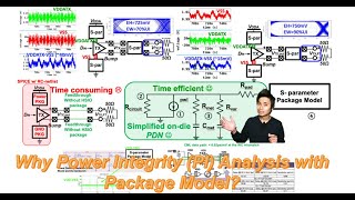
In the context of integrated circuit (IC) packaging, signal integrity (SI) is paramount to ensure high-quality signal transmission. Several sources contribute to signal integrity issues:
- Transmission Line Effects: PCB traces can behave like transmission lines when their lengths approach the wavelength of the signal. This leads to signal reflections and distortion.
- Crosstalk: This is the unwanted interference between adjacent traces that can degrade signal quality.
- Signal Reflection: Occurs due to impedance mismatches among the driver, trace, and receiver, resulting in portions of the signal reflecting back rather than reaching their intended destination.
- Electromagnetic Interference (EMI): Caused by both internal components and external sources, EMI can negatively impact signal quality, particularly in high-speed circuits.
- Package Parasitics: The design and characteristics of IC packages introduce parasitic inductance and capacitance, which can degrade signal integrity.
Addressing these sources is essential for optimal IC performance and reliability, especially as device speeds increase and circuits become more intricate.
Youtube Videos
Audio Book
Dive deep into the subject with an immersive audiobook experience.
Transmission Line Effects
Chapter 1 of 5
🔒 Unlock Audio Chapter
Sign up and enroll to access the full audio experience
Chapter Content
● Transmission Line Effects: Signal traces on the PCB can act like transmission lines. If the length of the trace becomes comparable to the signal wavelength, signal reflections can occur, causing distortion.
Detailed Explanation
Transmission line effects occur when the length of a signal trace on a printed circuit board (PCB) is significant compared to the wavelength of the signal being transmitted. When this happens, signals can reflect back instead of being fully transmitted to their destination, leading to distortions in the signal. This can disrupt communication between components, as the signal may not reach the receiver as intended or may arrive with errors.
Examples & Analogies
Think of it like a water pipe: if the pipe is very long compared to the speed of water flowing through it, any bumps or bends in the pipe can cause some of the water to splash back out instead of flowing straight through. This is similar to how signal reflections occur in long traces, affecting the clarity of the signal.
Crosstalk
Chapter 2 of 5
🔒 Unlock Audio Chapter
Sign up and enroll to access the full audio experience
Chapter Content
● Crosstalk: Crosstalk refers to unwanted coupling between adjacent signal traces. It occurs when signals from one trace interfere with signals in an adjacent trace, leading to signal degradation and potential errors.
Detailed Explanation
Crosstalk occurs when the electromagnetic field from one signal trace affects another nearby trace. This unwanted coupling can lead to interference, where the signal in one trace disturbs the signal in the adjacent trace. As a result, the integrity of the transmitted data can be compromised, causing errors or degradation in the overall signal quality.
Examples & Analogies
Imagine two people trying to have a conversation while standing too close together – if one person speaks loudly, they might accidentally interrupt or drown out the other person’s voice. Similarly, in electronic circuits, when signals are too close, they can interfere with each other, leading to confusion in data transmission.
Signal Reflection
Chapter 3 of 5
🔒 Unlock Audio Chapter
Sign up and enroll to access the full audio experience
Chapter Content
● Signal Reflection: Signal reflection happens when an impedance mismatch occurs between the driver, trace, and receiver. This leads to a portion of the signal being reflected back, causing interference.
Detailed Explanation
Signal reflection is caused by mismatches in impedance between different parts of a signal path – typically the driver (which sends the signal), the trace (the path it travels on), and the receiver (which receives the signal). When these components do not have matched impedances, some of the signal gets 'bounced back' instead of traveling forward, creating interference and potentially distorting the received signal.
Examples & Analogies
Think of it like a rubber ball being thrown against a wall. If the wall is not solid (like soft fabric), not much of the ball will bounce back, and it will continue down the path. However, if the wall is too hard or not aligned properly (like having mismatched impedances), the ball will bounce back wildly and won’t reach its target. This is like how an unmatched impedance can cause parts of the signal to reflect away instead of moving forward.
Electromagnetic Interference (EMI)
Chapter 4 of 5
🔒 Unlock Audio Chapter
Sign up and enroll to access the full audio experience
Chapter Content
● Electromagnetic Interference (EMI): EMI is caused by external or internal sources of interference, such as other circuits or power lines, which affect signal quality. This can be particularly problematic in high-frequency, high-speed circuits.
Detailed Explanation
Electromagnetic interference (EMI) can originate from various sources, both outside and within the electronic device. It can arise from other electronic circuits or power lines nearby that emit electromagnetic waves, which interfere with the intended signals in your circuit. This interference can significantly degrade signal quality, especially in high-speed applications where the clarity and precision of signals are critical.
Examples & Analogies
Think of it as trying to listen to your favorite music playlist while someone else is playing loud music nearby. The other music disturbs your experience and makes it hard to hear the tracks you love clearly. Similarly, EMI acts like that loud music, disrupting the clarity of electronic signals within a circuit.
Package Parasitics
Chapter 5 of 5
🔒 Unlock Audio Chapter
Sign up and enroll to access the full audio experience
Chapter Content
● Package Parasitics: IC packages introduce parasitic components such as inductance and capacitance that can degrade signal quality. The lead length, die size, and package type affect the severity of these parasitics.
Detailed Explanation
Package parasitics refer to the unwanted capacitive and inductive elements introduced by the physical packaging of integrated circuits (ICs). These parasitics can adversely affect the timing and integrity of signals due to unwanted capacitance or inductance, which can lead to delays or distortion in signal transmission. The design aspects of the IC package, such as lead lengths and material types, can influence the degree of these parasitic effects.
Examples & Analogies
Imagine trying to listen to a speech from someone who is standing inside a small room with poor acoustics. The sounds might echo or distort due to the reflective surfaces in the room. Similarly, in IC packages, parasitic components can create unwanted delays or distortions that muddy the quality of electrical signals.
Key Concepts
-
Transmission Line Effects: The behavior of traces comparable in length to signal wavelengths.
-
Crosstalk: Interference caused by adjacent traces affecting each other's signals.
-
Signal Reflection: Occurs due to impedance mismatches in the signal path.
-
Electromagnetic Interference: External noise affecting signal quality.
-
Package Parasitics: Inductive and capacitive elements that degrade signal integrity.
Examples & Applications
Example of Transmission Line Effects: A long trace acting as a transmission line reflects signals back due to its length compared to the signal wavelength.
Example of Crosstalk: Data corruption resulting from adjacent high-frequency signal traces.
Memory Aids
Interactive tools to help you remember key concepts
Rhymes
When traces grow long, don’t cause reflection wrong, keep them short, let signals go strong!
Stories
Once there were two signal traces that lived next to each other on a PCB. They often interfered, causing all types of confusion. They learned to keep the noise down by separating their paths and became reliable friends!
Memory Tools
Crosstalk, Reflection, EMI, Parasitics - Remember the acronym 'CREP' to know your signal enemies!
Acronyms
TESC - Transmission line, Electromagnetic interference, Signal reflection, Crosstalk. Remember this for signal integrity issues!
Flash Cards
Glossary
- Transmission Line Effects
Signal distortions that occur when the length of a PCB trace is comparable to the wavelength of the signal.
- Crosstalk
Unwanted coupling and interference between adjacent signal traces.
- Signal Reflection
The return of a portion of a signal due to impedance mismatches in a circuit.
- Electromagnetic Interference (EMI)
Noise and interference from external or internal sources affecting signal quality.
- Package Parasitics
Unwanted inductive and capacitive components introduced by IC packaging.
Reference links
Supplementary resources to enhance your learning experience.