
Free-Body Diagrams (FBDs)
Interactive Audio Lesson
Listen to a student-teacher conversation explaining the topic in a relatable way.
Understanding Free-Body Diagrams
🔒 Unlock Audio Lesson
Sign up and enroll to listen to this audio lesson

Welcome to our lesson on Free-Body Diagrams, or FBDs. They are tools we use to visualize the external forces acting on a system. Can anyone tell me why these diagrams are essential?

I think they're important because they help us understand all the forces on an object.
Exactly! FBDs provide clarity on the forces and moments acting on an isolated component. Now, let's discuss how to draw an FBD. What do you think are the first steps?

We should isolate the component first.
Correct! Isolating the subsystem is the first step. You also need to replace supports with force representations. Can anyone remember what kinds of forces we include?

Applied loads and reaction forces.
That's right! Additionally, we include dimensions and apply Newton's laws to set up equilibrium equations. Let’s summarize: isolate, represent forces, include dimensions, and apply equilibrium.
Applying Newton's Laws
🔒 Unlock Audio Lesson
Sign up and enroll to listen to this audio lesson

Now that we know how to draw an FBD, let’s delve into applying Newton's laws. Why do we apply these laws in our diagrams?

To calculate the forces and ensure everything is balanced?
Exactly! We are looking for equilibrium. Can anyone share an example where FBDs helped in analyzing forces?
When designing bridges, we need FBDs to ensure they can carry loads safely.
Great example. In mechanical design, FBDs help engineers decide how to strengthen components based on the forces represented. Remember: FBDs lead to better analyses!
Importance of Force Analysis
🔒 Unlock Audio Lesson
Sign up and enroll to listen to this audio lesson
Let’s connect FBDs to force analysis. How do FBDs contribute to understanding machine elements?
They help in figuring out the internal loads and stresses.
That's correct! By analyzing the forces in the FBD, engineers determine how components will behave under load. Why is this necessary for safety?
To ensure that parts don't fail during operation.
Exactly! Safety is paramount in design. Always consider FBDs as the first step to ensuring reliability in mechanical systems. Anyone can summarize the importance?
FBDs are crucial for visualizing forces and ensuring that designs are safe and efficient.
Introduction & Overview
Read summaries of the section's main ideas at different levels of detail.
Quick Overview
Standard
FBDs play a crucial role in mechanical design by helping engineers isolate components, represent forces, and apply equilibrium principles. Understanding how to draw and analyze FBDs is foundational for evaluating machine elements and ensuring their safety and functionality under various operational conditions.
Detailed
Free-Body Diagrams (FBDs) are crucial in the field of mechanical design, allowing engineers to visualize all external forces and moments that act on a specific machine element or system. The process of creating an FBD involves several key steps: isolating the component or subsystem, replacing supports and connections with appropriate representations of forces and moments, and incorporating all applied loads, reaction forces, and relevant dimensions. Furthermore, Newton's laws of motion are applied to set up equilibrium equations, which serve as the basis for further force analysis. This section also sets the stage for further exploration of force analysis techniques for various machine elements, including power screws, couplings, clutches, and brakes, all of which depend on understanding the interactions depicted in FBDs.
Youtube Videos


Audio Book
Dive deep into the subject with an immersive audiobook experience.
Overview of Free-Body Diagrams
Chapter 1 of 2
🔒 Unlock Audio Chapter
Sign up and enroll to access the full audio experience
Chapter Content
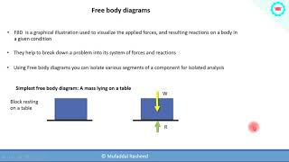
Free-body diagrams are essential tools in mechanical design, used to visualize all external forces and moments acting on a machine element or system.
Detailed Explanation
Free-body diagrams (FBDs) are graphical representations that illustrate all the forces and moments acting on a single entity, such as a mechanical component or a system. They help engineers and designers understand the interactions and effects of these external influences by simplifying complex systems into a manageable visual format. This visualization is crucial in analyzing the behavior of structures and mechanical systems under various loads.
Examples & Analogies
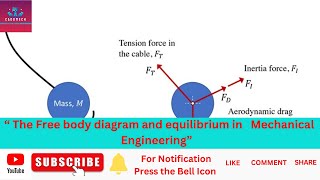
Think of a free-body diagram like a game of tug-of-war. Imagine each participant is pulling on the rope with different forces; the FBD shows the strength and direction of each pull clearly so that you can understand who has the advantage or how the rope will behave. It simplifies the complex scenario of multiple forces acting simultaneously into a single, clear picture.
Steps to Draw an FBD
Chapter 2 of 2
🔒 Unlock Audio Chapter
Sign up and enroll to access the full audio experience
Chapter Content
a. Steps to Draw an FBD:
● Isolate the component or subsystem
● Replace all supports and connections with appropriate force/moment representations
● Include applied loads, reaction forces, and dimensions
● Apply Newton's laws to set up equilibrium equations
Detailed Explanation
Creating an FBD involves several structured steps:
1. Isolate the Component: Start by identifying and isolating the specific part of the system you want to analyze. Imagine you are cutting out a piece of cake that you want to study closely.
2. Replace Supports and Connections: Any supports, connections, or interfaces with other components must be represented as forces or moments acting on the isolated component. This means drawing arrows to show how these connections affect the component you are studying.
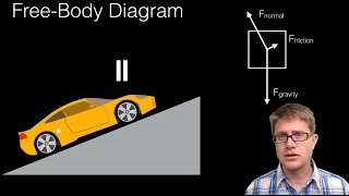
3. Include Loads and Forces: Next, depict all external forces that are applied, such as weights, friction, and any other influences that might affect the component. Indicate the direction and magnitude clearly.
4. Apply Newton’s Laws: Finally, use Newton's laws of motion to set up the equilibrium equations that will help to analyze the forces acting on the isolated component effectively. This step ensures that you can solve for unknown forces and understand the system's balance.
Examples & Analogies
Imagine you are figuring out how a hanging sign sways in the wind. First, isolate the sign by imagining it without any supporting wires or posts. Then, draw arrows to show how the weight of the sign pulls downward, while the wires pull upwards. You also need to show how the wind pushes against it. By using these steps, you can clearly visualize how everything works together, much like solving a mystery by breaking down the clues one by one.
Key Concepts
-
FBD Drawing Steps: Isolate the component, represent supports with forces, include applied loads and dimensions.
-
Newton’s Laws: Essential for deriving equilibrium equations in FBDs.
-
Equilibrium: Conditions where the sum of forces and moments results in zero.
Examples & Applications
An engineer uses an FBD to analyze a cantilever beam under a load to ensure it can support the weight without failing.
During bridge design, FBDs help determine the forces in cables and beams to ensure structural integrity.
Memory Aids
Interactive tools to help you remember key concepts
Rhymes
When forces act, don't be a fool, draw an FBD, it’s the golden rule.
Stories
Imagine a bridge architect drawing an FBD to ensure the bridge holds as cars cross, balancing all loads for safety.
Memory Tools
I-PRIME: Isolate, Replace, Include, Moments, Equilibrium – steps to draw an FBD.
Acronyms
FBD
Forces
Balance
Diagram – remember what it stands for!
Flash Cards
Glossary
- FreeBody Diagram (FBD)
A graphical representation used to visualize the forces acting on a particular body isolated from its surroundings.
- Newton's Laws
Three physical laws that together form the foundation for classical mechanics, describing the relationship between the motion of an object and the forces acting on it.
- Equilibrium
A state in which opposing forces are balanced, resulting in no net force acting on the system.
- Applied Loads
Forces that are applied to a system from external sources.
- Reaction Forces
Forces generated at supports and connections in response to the applied loads.
Reference links
Supplementary resources to enhance your learning experience.