
Analysis of Signal Propagation in RF Circuits
Interactive Audio Lesson
Listen to a student-teacher conversation explaining the topic in a relatable way.
Introduction to Signal Propagation
🔒 Unlock Audio Lesson
Sign up and enroll to listen to this audio lesson

Today we’re diving into the topic of signal propagation in RF circuits. Can anyone tell me what they think signal propagation means?

I think it has to do with how signals travel, right?
Exactly, it’s about the transmission of electromagnetic waves through various mediums! Remember that a few common mediums include transmission lines, waveguides, and even free space. Why do you think it's crucial to understand signal propagation in RF systems?

To reduce signal loss and interference?
Spot on! Understanding signal propagation helps us design efficient systems. Let’s unpack how transmission lines aid in this process.
Transmission Lines and Their Models
🔒 Unlock Audio Lesson
Sign up and enroll to listen to this audio lesson

Now, let’s focus on transmission lines. These are crucial for guiding signals. Can anyone name the elements that affect signal propagation in these lines?

Inductance, capacitance, resistance, and conductance!
Exactly! Remember the acronym LCRG to recall them easily. Each element plays a role in how the signal behaves. For example, capacitance affects the electric field. Can someone explain how resistance impacts this?

I guess resistance would cause power loss in the signal.
Correct! Losses due to resistance can affect the signal quality. Let’s look into the transmission line equations that help us quantify these behaviors.
Signal Propagation Speed
🔒 Unlock Audio Lesson
Sign up and enroll to listen to this audio lesson
Moving on, let’s discuss signal propagation speed. Who can tell me what phase velocity is?
It's the speed at which the wave phase - like peaks and troughs - travels through the line.
Great! And group velocity? How does that differ?
That's how fast the overall signal energy moves, right?
Exactly! Remember, phase velocity can differ from group velocity. And how about the significance of propagation delay?
It's the time it takes for a signal to get from one end to the other.
Exactly! These concepts are essential for understanding how to optimize our designs.
Waveguides and Their Characteristics
🔒 Unlock Audio Lesson
Sign up and enroll to listen to this audio lesson
Let’s turn our attention to waveguides. Who can share what waveguides are used for?
They guide high-frequency signals, like microwaves!
Exactly! Waveguides come with different propagation modes: TE, TM, and TEM. Can anyone explain the difference between TE and TM modes?
In TE modes, the electric field is transversely oriented, while in TM modes, it’s the magnetic field that's transverse.
Spot on! Keeping those straight is essential. Next, what defines the cutoff frequency in a waveguide?
Free Space Propagation
🔒 Unlock Audio Lesson
Sign up and enroll to listen to this audio lesson
Let’s conclude by discussing free-space propagation. What are some characteristics of signal propagation in free space?
It follows line-of-sight principles most of the time.
That's a key point! What else affects the signal as it travels through free space?
Path loss, right? Because distance and frequency both play a role.
Absolutely! Such losses must be accounted for in RF designs. Lastly, what environmental factors could we encounter?
Obstacles like trees or buildings can block or reroute signals.
Excellent! These real-world considerations are vital for effective RF system designs.
Introduction & Overview
Read summaries of the section's main ideas at different levels of detail.
Quick Overview
Standard
In this section, we explore the intricacies of signal propagation in RF circuits, including how electromagnetic waves are transmitted through different media. Key topics include transmission line models, signal propagation speed, waveguide characteristics, and the effects of free space on signal strength.
Detailed
Detailed Summary
Introduction to Signal Propagation
Signal propagation in RF circuits involves transmitting electromagnetic waves through mediums like transmission lines, waveguides, and free space. At high frequencies, factors such as the characteristics of the medium and the design of the circuit significantly affect signal behavior, making an understanding of these principles essential for effective RF system design.
Transmission Lines
In RF circuits, transmission lines guide signals between components. The behavior of signals in these lines is dictated by their characteristic impedance, distributed elements (resistances, inductances, capacitances), and propagation velocity.
Transmission Line Models
Transmission lines are modeled as distributed elements that exhibit interactions among inductance (L), capacitance (C), resistance (R), and conductance (G). These characteristics determine how electrical signals are transmitted and reflected.
Signal Propagation Speed
The speed at which signals propagate along a transmission line can vary based on the transmission line's dimensions and the medium's material properties. Key concepts include phase velocity and group velocity, which describe how individual wave phases and overall signal energy move, respectively.
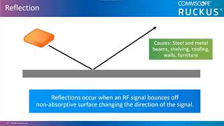
Reflection and Standing Waves
Impedance mismatches in transmission lines can cause signal reflections, leading to standing waves, which may result in power loss and signal degradation. Understanding the reflection coefficient and standing wave ratio is crucial to minimize these effects.
Waveguides
Waveguides are specialized structures for guiding high-frequency signals, particularly in microwave applications. They support different modes of propagation (TE, TM, TEM) and have defined cutoff frequencies that dictate operational effectiveness.
Free-Space Propagation
Free-space principles come into play when signals are transmitted over distances without physical guides. Factors influencing free-space propagation include path loss due to distance and frequency, as well as environmental obstacles that can cause reflections or obstructions.
Overall, recognizing the dynamics of signal propagation in these diverse environments allows engineers to design better RF systems that achieve efficient communication.
Youtube Videos

Audio Book
Dive deep into the subject with an immersive audiobook experience.
Introduction to Signal Propagation
Chapter 1 of 5
🔒 Unlock Audio Chapter
Sign up and enroll to access the full audio experience
Chapter Content
Signal propagation in RF circuits refers to the transmission of electromagnetic waves through various mediums, such as transmission lines, free space, or waveguides. At high frequencies (RF and HF), signal behavior is influenced by the characteristics of the medium, the physical layout of the circuit, and the properties of the components used in the circuit.
Understanding signal propagation is critical for designing efficient RF systems, ensuring minimal signal loss, distortion, and interference.
Detailed Explanation
This introduction explains what signal propagation means in the context of RF circuits. It refers to how electromagnetic waves move through different mediums, such as wires (transmission lines), space, or specially designed tubes (waveguides). At high frequencies, various factors influence how signals behave. Understanding these factors is crucial for designing systems that work well and avoid issues like losing signal strength or experiencing distortion.
Examples & Analogies
Think of signal propagation like sending a message through different channels: a whisper in a quiet room (free space), a shout in a crowded hallway (transmission line), and a secret note passed under a door (waveguide). Each method has its own challenges and effectiveness.
Transmission Lines and Signal Propagation
Chapter 2 of 5
🔒 Unlock Audio Chapter
Sign up and enroll to access the full audio experience
Chapter Content
In RF circuits, transmission lines are used to guide the signals between components, such as from a transmitter to an antenna or between stages in an amplifier. The behavior of signals in transmission lines is governed by their characteristic impedance and propagation velocity.
Detailed Explanation
Transmission lines are cables or circuits that connect various components, allowing signals to travel from one point to another. The properties of these lines, like their impedance and speed, determine how well they transmit signals. Impedance is like the resistance to the flow of water in a hose; it can affect how much signal gets through. Propagation velocity is how fast the signal travels along the line.
Examples & Analogies
Imagine a water pipe: the wider the pipe, the easier water flows. Similarly, a transmission line's impedance can restrict or facilitate the flow of electrical signals.
Transmission Line Models
Chapter 3 of 5
🔒 Unlock Audio Chapter
Sign up and enroll to access the full audio experience
Chapter Content
A transmission line is modeled as a series of distributed resistances, inductances, capacitances, and conductances. These elements influence how signals are transmitted along the line.
- Inductance (L): Represents the magnetic field created by the current flow in the transmission line.
- Capacitance (C): Represents the electric field formed between the conductors of the transmission line.
- Resistance (R): Represents the resistive losses in the conductors.
- Conductance (G): Represents the leakage current through the dielectric between the conductors.
Detailed Explanation
Transmission lines can be thought of as made up of multiple small components that affect how signals travel. Inductance relates to how the current creates a magnetic field, capacitance deals with the electric field between wires, resistance refers to energy lost due to heat, and conductance relates to how much current can leak through insulation. All these components together determine the overall performance of the transmission line.
Examples & Analogies
Picture a multi-layer cake: each layer (inductance, capacitance, resistance, conductance) contributes to the overall flavor and texture of the cake (the signal), affecting how it tastes (performs) as a whole.
Signal Propagation Speed and Group Velocity
Chapter 4 of 5
🔒 Unlock Audio Chapter
Sign up and enroll to access the full audio experience
Chapter Content
The speed of signal propagation along a transmission line depends on the material properties of the medium and the dimensions of the transmission line.
- Phase Velocity (vp): The phase velocity is the speed at which the phase of the signal (the individual peaks and troughs) propagates along the transmission line. It is given by:
vp=1LC
- Group Velocity (vg): The group velocity is the speed at which the overall signal energy propagates along the transmission line. It is often different from the phase velocity and is important for analyzing pulse propagation:
vg=dωdk
- Propagation Delay: The time it takes for a signal to travel from one point to another along the transmission line. It is given by:
τ=lvp
Detailed Explanation
Signal speed in transmission lines can be complex. There are two important types of speed: phase velocity, which indicates how fast individual waves move, and group velocity, which denotes how fast the overall signal moves. The propagation delay tells us how long it takes for a signal to travel a specific distance. These values depend on the materials used and the physical size of the transmission line.
Examples & Analogies
Consider a group of people walking down a hall (signal energy). The speed of each person's movement (phase velocity) might differ from the speed at which the entire group moves together (group velocity) as they follow each other. Propagation delay is like counting how long it takes for the last person to reach the hall's end.
Reflection and Standing Wave Formation
Chapter 5 of 5
🔒 Unlock Audio Chapter
Sign up and enroll to access the full audio experience
Chapter Content
When a signal encounters an impedance mismatch along the transmission line, part of the signal is reflected back toward the source. This reflection leads to the formation of standing waves, which can cause signal loss and interference.
- Reflection Coefficient: The reflection coefficient Γ describes the proportion of the signal that is reflected due to an impedance mismatch:
Γ=Zload−Z0Zload+Z0
- Standing Wave Ratio (SWR): The SWR describes the ratio of the maximum to minimum voltage levels along the transmission line due to reflections.
Detailed Explanation
When signals encounter a change in impedance along a transmission line, part of the signal reflects back towards the source. This can create standing waves, which are patterns that form when two waves interfere with each other. The reflection coefficient helps measure how much of the signal is reflected, and the Standing Wave Ratio (SWR) indicates how perfectly the impedance matches, with a lower number representing better matching and less reflection.
Examples & Analogies
Imagine throwing a pebble into a still pond: if the pond's surface remains unchanged, the ripples (signal) spread out evenly. But if there's a rock (impedance mismatch) in the water, some ripples bounce back, creating a conflicting pattern (standing waves).
Key Concepts
-
Signal Propagation: Transmission of electromagnetic waves through various media.
-
Propagation Speed: Differentiation between phase and group velocity influencing signal transmission.
-
Transmission Line Models: Characteristic impedance, distributed elements, and the mathematical equations governing transmission.
-
Waveguides: Structures for guiding high-frequency signals with unique propagation modes and cutoff frequencies.
-
Free-Space Signal Propagation: Effects of distance, frequency, and environmental conditions on signal transmission.
Examples & Applications
A radio station transmits signals through a transmission line to its antenna, where the choice of transmission line affects the quality of the broadcast.
In microwave communication, waveguides are utilized to ensure efficient transmission, avoiding losses associated with transmission lines.
Memory Aids
Interactive tools to help you remember key concepts
Rhymes
If the wave should not pause, check its cause – impedance's laws!
Stories
Imagine a race where signals travel through paths, some straight and others bent by obstacles. The fastest runners are those in clear waveguides, while those in transmission lines feel the resistance of the wind.
Memory Tools
Remember 'LCRG' for Transmission Line elements: L for Inductance, C for Capacitance, R for Resistance, and G for Conductance.
Acronyms
Use 'WAVE' to remember Waveguide characteristics
Wavelength
Amplitude
Velocity
and Energy.
Flash Cards
Glossary
- Transmission Line
A specialized cable or system of cables designed to carry electrical signals from one point to another.
- Characteristic Impedance
The impedance that a transmission line exhibits, determining how signals are transmitted along it.
- Phase Velocity
The speed at which the phase of a wave propagates through space.
- Group Velocity
The speed at which the overall shape of a wave's amplitudes — known as the modulation envelope — propagates through space.
- Impedance Mismatch
Occurs when the load impedance and the characteristic impedance of the transmission line do not match, leading to signal reflections.
- Cutoff Frequency
The frequency below which a particular mode will not propagate in a waveguide.
- Path Loss
The reduction in power density of an electromagnetic wave as it propagates through space.
Reference links
Supplementary resources to enhance your learning experience.