
Design of Steel Columns Under Axial Loads
Enroll to start learning
You’ve not yet enrolled in this course. Please enroll for free to listen to audio lessons, classroom podcasts and take practice test.
Interactive Audio Lesson
Listen to a student-teacher conversation explaining the topic in a relatable way.
Introduction to Steel Columns
🔒 Unlock Audio Lesson
Sign up and enroll to listen to this audio lesson

Welcome everyone! Today, we're diving into the design of steel columns under axial loads. Can anyone tell me why steel columns are important in construction?

They support loads from beams and slabs, right?
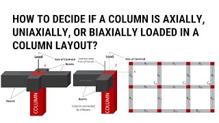
Exactly! They're essential for bearing vertical loads and ensuring structural stability. Remember, we use terms like axial loads, which primarily refer to the compressive forces on these columns.

What happens if the design is not done properly?
Great question! Poor design can lead to buckling or even failure under load. That's why we need to follow a systematic design process, starting with calculating the factored axial load, or Pu.
Calculating Factored Axial Load
🔒 Unlock Audio Lesson
Sign up and enroll to listen to this audio lesson

Let's move on to calculating Pu. Can anyone remind us how we calculate the factored axial load?

Is it the applied load multiplied by a safety factor?
Exactly! The formula is Pu = applied load × partial safety factor according to codes. This ensures we account for uncertainties in loading conditions.

What does a partial safety factor do?
It provides a margin of safety, ensuring that our designs can withstand unexpected loads. Always remember to check your codes for the appropriate factors!
Designing Steel Sections
🔒 Unlock Audio Lesson
Sign up and enroll to listen to this audio lesson
Once we have Pu, the next step is selecting a suitable section. What sections are often used?
Types like ISHB and ISMB are common, right?
Correct! When selecting sections, we need to ensure that the design compressive strength, Pd, exceeds the calculated Pu. We also have to check for the slenderness ratio, λ.
How do we calculate slenderness ratio?
Great inquiry! The slenderness ratio is calculated as: λ = effective length / least radius of gyration (r). Keeping up with these criteria ensures stability against buckling.
Built-up Columns
🔒 Unlock Audio Lesson
Sign up and enroll to listen to this audio lesson
Now, let’s discuss built-up columns. When would you choose them over single sections?
Maybe for higher loads or longer columns?
Exactly! Built-up columns are designed from multiple sections and need careful arrangement to avoid torsion. They should also include lacing or battens for stability.
What are lacing and battens used for?
Good question! Lacing connects the sections and helps prevent buckling while battens reinforce the connections. Always ensure they are designed to handle shear forces!
Base Design
🔒 Unlock Audio Lesson
Sign up and enroll to listen to this audio lesson
Lastly, let’s talk about base design. Why is the base important?
It’s where the column connects to the foundation, right?
Exactly! The base needs to efficiently transfer loads to the foundations. We have two main types: slab bases for moderate loads and gusseted bases for heavier loads.
How do we decide which base to use?
Excellent question! Choose based on the load requirements. Each type has distinct design steps to ensure effective load transfer. Remember to account for the design area and thickness!
This is quite a lot to remember!
It is! But with practice and by summarizing key points, it becomes manageable.
Introduction & Overview
Read summaries of the section's main ideas at different levels of detail.
Quick Overview
Standard
The section explores the design processes for steel columns, including both single and built-up sections. It details the steps involved in determining design strength, slenderness ratio, and local buckling considerations, as well as serviceability checks. Additionally, it highlights different configurations and the importance of stability in column design.
Detailed
Design of Steel Columns Under Axial Loads
Steel columns are essential components in construction, serving as critical vertical load-bearing members. The proper design of these columns is crucial for ensuring structural safety and preventing failures due to buckling. This section discusses the design of both single rolled steel sections and built-up columns.
Single Rolled Steel Sections
Typical sections such as ISHB, ISMB, ISJC, UC, and H-sections are utilized for their high resistance to buckling. The design process includes the following steps:
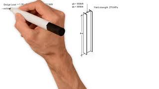
1. Calculate the Factored Axial Load (Pu) using the formula:
Pu = applied load × partial safety factor (as per relevant codes).
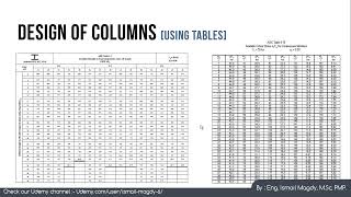
2. Select a Suitable Section from tables, ensuring that the design compressive strength (Pd) exceeds the calculated Pu.
3. Check the Slenderness Ratio (λ) using the formula:
λ = effective length / least radius of gyration (r).
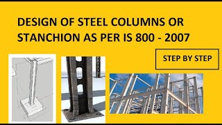
4. Verify Local Buckling by following code requirements (e.g., IS 800-2007).
5. Check Serviceability to confirm that deflection and lateral stability meet the necessary standards.
Built-up Columns
Used when higher load capacity or longer lengths are required, built-up columns consist of two or more steel sections connected by lacing or batten plates. The design process involves:
- Choosing a symmetrical arrangement to avoid torsional issues.
- Combining section properties to ensure adequate stability by calculating the total area, moment of inertia, and radius of gyration about the principal axes.
- Providing adequate spacing to prevent local buckling.
- Conducting stability checks similar to single sections but using combined properties.
Design of Lacing and Battens
Lacing aids in providing lateral stability to built-up columns. Designs should consider angles between 40° and 70°, and members need to be designed adequately for shear. Battens serve to connect section elements providing additional stability as well.
Beam-Columns
Columns may have significant bending moments due to external loads, requiring checks for combined axial and bending capacities using appropriate interaction equations.
Base Design
Steel columns transfer loads via various base plate designs including slab and gusseted bases, each having distinct applications based on load types. Key design steps must ensure appropriate plate sizing and connection methods to facilitate vertical load transfer effectively.
In conclusion, the section provides comprehensive guidance on the design of steel columns and their bases, adhering to modern structural codes.
Youtube Videos
Audio Book
Dive deep into the subject with an immersive audiobook experience.
Introduction to Steel Columns
Chapter 1 of 5
🔒 Unlock Audio Chapter
Sign up and enroll to access the full audio experience
Chapter Content
Steel columns are critical vertical load-bearing members designed to support compression forces from slabs, beams, or trusses. Proper design ensures structural safety against buckling and compressive failure.
Detailed Explanation
Steel columns are essential structural elements that carry vertical loads. They are designed to handle compression, which is the force that pushes down on them. Effective design is crucial because it helps the columns withstand bending, breaking, or buckling when they bear the loads. Understanding their role is the first step in ensuring that buildings and structures remain safe and stable.
Examples & Analogies
Think of steel columns like the legs of a table. Just as table legs support the weight of the table and everything on it, steel columns support various structures like bridges or buildings. If the legs aren’t strong enough or designed properly, the table could wobble or collapse.
Single Rolled Steel Sections
Chapter 2 of 5
🔒 Unlock Audio Chapter
Sign up and enroll to access the full audio experience
Chapter Content
Typical Sections: ISHB, ISMB, ISJC, UC, or H-section, chosen for their high buckling resistance.
Detailed Explanation
Single rolled steel sections are specific shapes of steel that have been manufactured to provide optimal performance in load-bearing applications. Examples include ISHB (Indian Standard Horizontal Beams), ISMB (Indian Standard Medium Beams), and others categorized generally as H-sections. These sections are selected because they resist buckling efficiently, which is a failure mode that can occur when a column is too slender or carries too much load.
Examples & Analogies
Selecting the right type of steel section is like choosing the right size of a straw for drinking a thick smoothie. A wider straw can handle thicker drinks without collapsing, similar to how a beefy steel section can handle more load without buckling.
Design Steps for Steel Columns
Chapter 3 of 5
🔒 Unlock Audio Chapter
Sign up and enroll to access the full audio experience
Chapter Content
- Calculate Factored Axial Load Pu Pu = applied load × partial safety factor (as per code). 2. Select Section: Using tables, check that the design compressive strength Pd of the section (based on buckling class and slenderness ratio) exceeds Pu. 3. Check Slenderness Ratio (λ): λ = (effective length) / (least radius of gyration, r). 4. Verify Local Buckling: Ensure section is adequate for local buckling by code (e.g., IS 8002007). 5. Check Serviceability: Deflection and lateral stability as required.
Detailed Explanation
The design of steel columns involves a systematic process: First, we calculate the factored axial load, which is the load the column must support taking into account safety factors. Next, we select a section from design tables to ensure that it can handle this load. The slenderness ratio must be checked to confirm that the column is not too slender to buckle under load. We also need to verify that the column can resist local buckling and check the serviceability for deflection and stability during use.
Examples & Analogies
Designing a column is like preparing a recipe. First, you need to know how many servings (the load) you need to prepare. Then, you choose the right ingredients (the steel section). After that, you measure each ingredient (slenderness ratio) to make sure your dish doesn’t turn out too bland or too overcooked (prevent buckling or excessive deflection).
Multiple Rolled Steel Sections
Chapter 4 of 5
🔒 Unlock Audio Chapter
Sign up and enroll to access the full audio experience
Chapter Content
Used when higher load capacity or longer column length is required. Configuration: Two or more sections (e.g., channels, angles, or beams) spaced apart and connected by lacing or batten plates.
Detailed Explanation
When a single steel section isn’t adequate for heavier loads or longer spans, multiple steel sections are used together. This configuration can be made with materials like channels or angles, which are connected in a way that maintains stability and strength under load. The design must account for how these sections interact and work together, ensuring they can handle the forces applied without failing.
Examples & Analogies
Think of this like stacking several boards to create a stronger table. Just as you would use multiple boards held together to support a heavier load, multiple steel sections can work in concert to support greater weights or span longer distances without compromising stability.
Design for Overall Stability
Chapter 5 of 5
🔒 Unlock Audio Chapter
Sign up and enroll to access the full audio experience
Chapter Content
Select Section Arrangement: Symmetrical, to avoid torsion/buckling. Combine Section Properties: Calculate total area, moment of inertia, and radius of gyration about principal axes. Design for Overall Stability: As for single columns, but use combined properties. Spacing: Adequate spacing provided to prevent local buckling.
Detailed Explanation
In the design of built-up columns, it’s important to arrange the sections symmetrically to minimize any twisting (torsion) that could lead to buckling. The physical properties of the combined sections should be calculated to understand how they will react to loads. Spacing is also critical; it should be designed to prevent any local buckling between the sections.
Examples & Analogies
This is similar to how you would arrange books on a shelf. If all the larger, heavier books are at one end, the shelf might tip or bow. Placing the books evenly (symmetrically) allows for a stable structure, just like how evenly spaced steel sections contribute to stability in columns.
Key Concepts
-
Design Process: Essential steps include calculation of Pu, selection of section, slenderness checks, and serviceability considerations.
-
Single vs Built-up Columns: Understanding when to use each based on load requirements and length.
-
Local Buckling: A critical factor in ensuring designed sections are adequate for expected loads.
-
Base Design: Important for effective load transfer from columns to foundations.
Examples & Applications
An example of calculating factored axial load (Pu) for a steel column subjected to 100 kN axial load with a safety factor of 1.5 would yield Pu = 100 kN * 1.5 = 150 kN.
When designing a built-up column to support heavy loads, the architect might choose to use IS sections combined with lacing members to ensure stability.
Memory Aids
Interactive tools to help you remember key concepts
Rhymes
In columns strong and steel, they stand, designed to carry load on land.
Stories
Imagine a tall building where steel columns rise through floors, continuously checked and designed to ensure their strength under the heavy load, working together with the foundation to stand tall against winds and tremors.
Memory Tools
Remember the steps for column design: 'Calculate, Select, Check, Verify, Serve' (CSCVS).
Acronyms
Pu - Properly Use safe design measures.
Flash Cards
Glossary
- Factored Axial Load (Pu)
The load applied to a column, multiplied by a partial safety factor to account for uncertainties.
- Design Compressive Strength (Pd)
The maximum compressive load a column section can support without failure.
- Slenderness Ratio (λ)
A dimensionless ratio that indicates a column's propensity to buckle, calculated as the effective length divided by the least radius of gyration.
- Local Buckling
A failure mode that occurs when parts of a structural member buckle at less than the overall buckling load.
- Serviceability
Consideration of a structure's performance under load conditions regarding deflection and stability.
- Lacing
Diagonal connections used in built-up columns to provide lateral stability.
- Battens
Flat plates used to connect individual sections in built-up columns.
Reference links
Supplementary resources to enhance your learning experience.