
Beam Design Formulas with Shear and Moment Diagrams
Enroll to start learning
You’ve not yet enrolled in this course. Please enroll for free to listen to audio lessons, classroom podcasts and take practice test.
Interactive Audio Lesson
Listen to a student-teacher conversation explaining the topic in a relatable way.
Introduction to Shear Forces
🔒 Unlock Audio Lesson
Sign up and enroll to listen to this audio lesson

Today, we’ll start with understanding shear forces in beams. Shear forces are internal forces that act parallel to a beam's cross-section. Can anyone tell me why these forces are critical in beam design?

They help us figure out how much load a beam can take before it fails, right?
Exactly! We measure shear forces to ensure that beams can withstand different loads without failing. A mnemonic to remember this is ‘SHARE’ - Shear Helps Assess Resistance and Efficiency in structures.

What happens if the shear force exceeds a certain point?
Good question! If it exceeds the material's limit, the beam could shear, leading to structural failure. That’s why we create shear diagrams to visualize these forces.

How do we calculate the shear force at any point?
To find shear force at a point on a beam, we sum the vertical forces acting on one side of that point. Remember, understanding these calculations is crucial for ensuring structural integrity.
Let's summarize: Shear forces are internal forces acting parallel to a beam, crucial for stability. Always remember the mnemonic 'SHARE' to keep their role clear in mind.
Understanding Moment Diagrams
🔒 Unlock Audio Lesson
Sign up and enroll to listen to this audio lesson

Now, let’s move to moments. A bending moment at a section of the beam indicates the tendency of the beam to rotate. Can anyone provide a brief definition of bending moments?

It's the force that causes the bending in beams, right?
Correct! We measure the bending moment using the formula: Moment = Force x Distance. A helpful mnemonic for this is ‘MOM’ – Moments Occur from Moments! Can anyone think of why knowing these moments is important?
Understanding them helps us know how much the beam can bend without breaking?
Exactly right! With moment diagrams, we can visualize the relationship between loading conditions and the moments throughout the beam's length. Each peak in a moment diagram indicates a point of maximum bending.
How do we practically apply these moments in design?
We use the bending moment values to select suitable materials and sizes for beams that will safely support the expected loads. Summarizing for today: Moments cause beams to bend and are crucial for design calculations. Keep 'MOM' in mind as a quick reminder!
Creating Shear and Moment Diagrams
🔒 Unlock Audio Lesson
Sign up and enroll to listen to this audio lesson
Let’s learn how to create shear and moment diagrams from a given load. First, we analyze the loads acting on a beam. Can someone tell me how we start this process?
By calculating the reactions at the supports?
Exactly! Knowing the support reactions is essential. Next, we plot these along the beam's length. As we cross each load, we adjust our shear force calculation upwards or downwards depending on the load type. Who remembers how to adjust for point loads?
We subtract for loads acting downward and add for those acting upward.
Correct! Now, once we have the shear diagram, we can determine the moments at different points. The area under the shear diagram gives us the moment. What might be a useful way to visualize these diagrams?
By using graph paper to plot them clearly?
Precisely! Clear graphs make it easy to understand how forces change along the beam. So, to summarize: Start with support reactions, plot shear forces and adjust accordingly, and then use areas to find moments.
Applications in Real World
🔒 Unlock Audio Lesson
Sign up and enroll to listen to this audio lesson
Let’s relate shear and moment diagrams to real-world scenarios. How might these diagrams be used in designing a bridge?
They would help determine how much weight the bridge can support and where reinforcements might be needed.
Absolutely right! Engineers rely on precise diagrams to avoid potential failures. Can anyone think of another application of these concepts?
Maybe in building frames?
Exactly! Buildings have loads distributed across beams, and shear and moment diagrams help us ensure stability and safety. Never underestimate their importance! Quick recap: Real-world applications include bridges and buildings, guiding safe designs to withstand forces.
Introduction & Overview
Read summaries of the section's main ideas at different levels of detail.
Quick Overview
Standard
The section provides a comprehensive overview of beam design formulas, emphasizing the importance of shear and moment diagrams in structural analysis. By understanding these diagrams, civil engineering students can accurately determine the forces acting on a beam and design safer structures.
Detailed
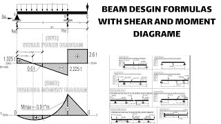
Beam Design Formulas with Shear and Moment Diagrams
This section delves into the fundamental aspects of beam design in civil engineering, particularly focusing on the importance of shear and moment diagrams. Beam design is critical for ensuring the safety and efficiency of structures, and understanding how to create and interpret shear and moment diagrams is essential for any engineer.
Key Points Covered:
- Shear Forces: The internal forces that act parallel to the beam's cross-section and can cause it to shear or
Youtube Videos


Audio Book
Dive deep into the subject with an immersive audiobook experience.
Introduction to Beam Design
Chapter 1 of 5
🔒 Unlock Audio Chapter
Sign up and enroll to access the full audio experience
Chapter Content
Beam design is crucial in structural engineering, enabling structures to withstand loads effectively.
Detailed Explanation
Beam design involves creating structures that carry loads across distances. It’s important because these structures need to handle various forces without collapsing. Engineers must consider the materials used, the types of loads (like weight), and environmental factors to ensure safety and functionality.
Examples & Analogies
Think of a bridge: the beams support the roadway, and if they are not designed correctly, the bridge could sag or even fail under the weight of cars and trucks. Just like a strong bookshelf needs solid shelves to hold books without bending or falling, beams must be designed properly to support their loads.
Understanding Shear and Moment Diagrams
Chapter 2 of 5
🔒 Unlock Audio Chapter
Sign up and enroll to access the full audio experience
Chapter Content
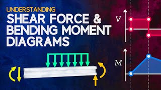
Shear and moment diagrams graphically represent the internal forces within a beam due to applied loads.
Detailed Explanation
Shear diagrams show how the shear force changes along the length of the beam, while moment diagrams illustrate the bending moment at various points. These diagrams are essential for understanding how loads affect beam behavior and are critical for safe design.
Examples & Analogies
Imagine holding a ruler at both ends. If you press down in the middle, the ruler bends, creating a moment (bending) and shear (force) along its length. The diagrams help visualize that behavior so engineers can avoid overstressing the beam.
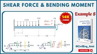
Calculating Shear Forces
Chapter 3 of 5
🔒 Unlock Audio Chapter
Sign up and enroll to access the full audio experience
Chapter Content
To find shear forces, calculate the vertical forces acting on the beam at specific points.
Detailed Explanation
Shear forces are calculated by summing the vertical forces acting on the beam. For any given cut in a beam, the shear force is the total upward reaction minus the downward forces on one side of the cut. This ensures that we know how much internal force exists at that section of the beam.
Examples & Analogies
Consider a restaurant waiter carrying a tray. The force of the tray on their hands is like the shear force acting at that point. If more dishes are added (a downward force), the waiter must adjust their grip to maintain balance, similar to how engineers must account for forces in beam design.
Calculating Bending Moments
Chapter 4 of 5
🔒 Unlock Audio Chapter
Sign up and enroll to access the full audio experience
Chapter Content
Bending moments are calculated using the shear force and distances along the beam.
Detailed Explanation
Bending moments are found by integrating the shear over the length of the beam or calculating moments about particular points. This tells us how much 'bending' is experienced at any location due to applied loads. It’s crucial for determining where failure may occur under load.
Examples & Analogies
Think about a flexible straw. When you bend it, the area where you are bending experiences a moment. If the moment exceeds the straw’s capacity, it will fold or snap. Engineers must ensure our beams can handle the bending moments they experience similarly.
Applying Beam Design Formulas
Chapter 5 of 5
🔒 Unlock Audio Chapter
Sign up and enroll to access the full audio experience
Chapter Content
Engineers use specific formulas to calculate the design of beams based on shear and moment calculations.
Detailed Explanation
Using the calculated shear forces and bending moments, engineers apply formulas such as the moment-curvature relationship to determine beam dimensions and material properties necessary to achieve safety and serviceability. This is also where factors of safety come into play.
Examples & Analogies
Designing a beam is like creating a new recipe. You can’t just throw in ingredients without measurements, or the dish might not turn out right. Similarly, engineers can't just guess beam sizes; they have to use calculations to ensure their designs are safe and effective.
Key Concepts
-
Shear Forces: Internal forces parallel to a beam's cross-section.
-
Bending Moments: Moments that cause a beam to bend.
-
Shear Diagrams: Visual aids used to illustrate shear forces along a beam.
-
Moment Diagrams: Graphical representations of how bending moments vary along a beam.
Examples & Applications
Example 1: A simply supported beam with a central point load of 10 kN has a bending moment maximum at the center, calculated using M = (Load x Length)/4.
Example 2: Analyzing a cantilever beam under a uniform load allows the use of moment equations to determine the maximum moment at the fixed end.
Memory Aids
Interactive tools to help you remember key concepts
Rhymes
In shear, forces don’t spread, keep beams safe instead!
Stories
Imagine a bridge held up by beams that bend without a care, shear forces keep it stable, avoiding a fall from despair.
Memory Tools
PARE: Plotting Areas Reveals Everything for moments and shear diagrams!
Acronyms
BENDING
Beams Endure as Needed by Designed Ingenious Network of Gravity.
Flash Cards
Glossary
- Shear Force
An internal force that acts parallel to the cross-section of a beam, potentially leading to shearing.
- Bending Moment
The internal moment that induces bending in a beam due to external loads.
- Shear Diagram
A graphical representation showing how shear forces vary along the length of a beam.
- Moment Diagram
A graphical representation illustrating how bending moments change along the beam.
- Load
The external force or weight applied to a beam.
Reference links
Supplementary resources to enhance your learning experience.