
USEFUL FORMULAS
Enroll to start learning
You’ve not yet enrolled in this course. Please enroll for free to listen to audio lessons, classroom podcasts and take practice test.
Interactive Audio Lesson
Listen to a student-teacher conversation explaining the topic in a relatable way.
Introduction to Beam Design Formulas
🔒 Unlock Audio Lesson
Sign up and enroll to listen to this audio lesson

Today, we will learn about essential formulas related to beam design. Can anyone tell me why understanding shear and moment is crucial?

I think it's because it helps us ensure safety in structures?
Exactly! By analyzing shear and moment, we can determine how a beam will react under loads. Remember the acronym 'S-M' for Shear-Moment!

What role do shear and moment diagrams play in this?
Great question! These diagrams visually represent how shear and moments vary along the length of a beam. Understanding them is a critical part of our analysis.
Let's summarize: 'S-M diagrams are crucial for analyzing the behavior of beams under load'.
Understanding Shear Forces
🔒 Unlock Audio Lesson
Sign up and enroll to listen to this audio lesson

Now let's focus on shear forces. Can anyone explain what a shear force is?

Isn't it the force that acts perpendicular to the beam?
Correct! This force tends to cause one section of the beam to slide past another. Can you connect this to an example of a load on a beam?

If we apply a load in the middle, that would create shear forces at the supports!
Absolutely! Remember, 'Shear is near, at the beam's pier'. Now, let's summarize today's topic: 'Shear forces act perpendicular to the beams and are crucial in determining beam stability.'
Bending Moments Explained
🔒 Unlock Audio Lesson
Sign up and enroll to listen to this audio lesson
Next, let’s discuss bending moments. What do we mean by bending moments, anyone?
It's the internal moment that resists the bending caused by loads, right?
Exactly! This internal force helps us understand how much the beam bends under load. Can anyone name a formula associated with bending moments?
I think it involves downward force times the distance to the point of interest?
Spot on! The formula for computing bending moment is: M = F × d, where M is the moment, F is the force, and d is the distance. Let's summarize that: 'Bending moment is crucial for predicting how a beam will respond and is calculated as Force times Distance.'
Applying Shear and Moment Diagrams
🔒 Unlock Audio Lesson
Sign up and enroll to listen to this audio lesson
Finally, how about we learn how to create shear and moment diagrams? Who can outline the steps required?
First, we must calculate all the reactions at the supports.
Then we would draw the shear diagram by calculating the shear force at various points.
Exactly, and once we have the shear diagram, we can create the moment diagram by integrating the shear force. Remember: 'Integrate Shear for the Moment!' Now, summarize the process for us.
Calculate reactions, draw the shear diagram, then integrate for the moment diagram!
Fantastic! This comprehensive understanding will aid in designing safer structures.
Introduction & Overview
Read summaries of the section's main ideas at different levels of detail.
Quick Overview
Standard
In this section, we delve into essential formulas used for beam design, focusing on the relationship between shear forces and bending moments in structural elements. Understanding these formulas is crucial for engineers in accurately predicting structural behavior under various loads.
Detailed
Useful Formulas
In the realm of structural engineering, particularly in beam design, certain formulas play a critical role in understanding the behavior of beams under load. This section explores the fundamental relationships between shear forces and bending moments, facilitated by shear and moment diagrams. The comprehension of these relationships is indispensable for engineers as they ensure that structures are both safe and efficient under projected load scenarios. This section not only provides the necessary formulas but also emphasizes their practical applications in real-world structural analysis.
Youtube Videos


Audio Book
Dive deep into the subject with an immersive audiobook experience.
Introduction to Beam Design
Chapter 1 of 3
🔒 Unlock Audio Chapter
Sign up and enroll to access the full audio experience
Chapter Content
Beam design is crucial in civil engineering, as it involves calculating the strength and stability of beams under various loads.
Detailed Explanation
Beam design refers to the process of ensuring that a beam can support the loads it encounters without failing. This involves understanding how beams behave when subjected to forces. Engineers use specific formulas to calculate parameters like bending moments and shear forces, which help in determining the size and material of the beam required for safety and efficiency.
Examples & Analogies
Imagine a simple bookshelf. If you put too many heavy books on one shelf, the wood may bend or even break. Engineers use beam design formulas to determine how thick or strong the bookshelf needs to be to support the weight without collapsing.
Shear and Moment Diagrams
Chapter 2 of 3
🔒 Unlock Audio Chapter
Sign up and enroll to access the full audio experience
Chapter Content
Shear and moment diagrams graphically represent the shear force and bending moment along the beam.
Detailed Explanation
Shear and moment diagrams are essential tools for visualizing how forces act on a beam. The shear diagram shows how the shear force varies along the length of the beam, while the moment diagram depicts the bending moment at various points. Engineers create these diagrams by analyzing the loading conditions and applying equilibrium equations, which help in identifying critical points where the maximum shear and moments occur.
Examples & Analogies
Think of a seesaw in a park. The way it tilts when a person sits on one side can be compared to a shear force. The bending or curvature of the seesaw shows its bending moment. By understanding these diagrams, engineers can ensure the seesaw is built to withstand the loads without breaking.
Important Beam Formulas
Chapter 3 of 3
🔒 Unlock Audio Chapter
Sign up and enroll to access the full audio experience
Chapter Content
Key formulas include the bending stress formula and shear stress formula, which are essential for determining safe material use.
Detailed Explanation
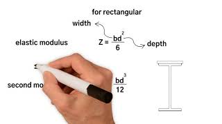
The bending stress formula, typically represented as σ = M/S, relates to the internal stress experienced by a beam due to bending. Here, σ is the bending stress, M is the moment about the neutral axis, and S is the section modulus of the beam. The shear stress formula, τ = V/Q, expresses how shear force translates into stress over the beam's cross-section, where τ is shear stress, V is the applied shear force, and Q is the first moment of area about the neutral axis. These formulas are critical in ensuring that beams can safely carry expected loads.
Examples & Analogies
Consider a bridge. Engineers use bending and shear stress formulas to calculate how much weight the bridge can hold. If a truck drives over the bridge, the calculations assure that the bridge will not collapse under the pressure, similar to how a doctor ensures a medicine dosage is safe for a patient based on weight.
Key Concepts
-
Shear Forces: Forces acting perpendicular to a beam's axis, important for stability.
-
Bending Moments: Internal forces that resist bending, related to loads and distances.
-
Shear Diagrams: Visual tools that represent shear force variations along beams.
-
Moment Diagrams: Visual tools showing changes in bending moment across beams.
Examples & Applications
Example 1: A simply supported beam with a load at its center generates shear forces at the supports and a maximum bending moment at the center.
Example 2: The calculation of a beam's bending moment can be illustrated using a cantilever beam under a point load at the free end.
Memory Aids
Interactive tools to help you remember key concepts
Rhymes
Shear near, at the pier!
Stories
Imagine a bridge made of beams where the load is dropped, the beams bend and shear forces come to play, ensuring the bridge compresses and expands, yet doesn't sway.
Memory Tools
Sister McDonald's Beams: Shear-Moment-Design.
Acronyms
BAM
Bending And Moments.
Flash Cards
Glossary
- Shear Force
A force that acts perpendicular to the axis of a beam, causing one section of the beam to slide past another.
- Bending Moment
An internal moment that induces bending in a beam, calculated as force multiplied by the distance from the point of interest.
- Shear Diagram
A graphical representation showing how shear forces vary along the length of the beam.
- Moment Diagram
A graphical representation showing how bending moments change along the length of the beam.
Reference links
Supplementary resources to enhance your learning experience.