
Analog Filter Design Basics
Interactive Audio Lesson
Listen to a student-teacher conversation explaining the topic in a relatable way.
Components Used in Analog Filters
🔒 Unlock Audio Lesson
Sign up and enroll to listen to this audio lesson

Let's discuss the components used in analog filters. What do you think are the primary elements that comprise these filters?

Are those just resistors and capacitors?
Good! Yes, we use resistors and capacitors, but also inductors and operational amplifiers. Can anyone tell me how these components function together?

I think resistors limit current and capacitors store energy.
Exactly! Resistors restrict current flow, while capacitors can charge and discharge, affecting how signals pass through. Let’s remember this with the acronym **RCIO** for Resistors, Capacitors, Inductors, and Op-Amps.
Understanding Cutoff Frequency
🔒 Unlock Audio Lesson
Sign up and enroll to listen to this audio lesson

Now, moving on to the cutoff frequency. It's a critical parameter in filter design. Does anyone know what it represents?

Is it where the filter starts to weaken the signal?
That's right! The cutoff frequency, denoted as **fc**, is the point at which the filter begins to attenuate the input signal. It essentially marks the boundary between the passband and the stopband.

So, does changing the value of the resistors or capacitors affect the cutoff frequency?
Yes, it does! By altering these components, you can effectively change the cutoff frequency. Here's a mnemonic: **C-RES** – Capacitors and Resistors influence the filter's Cutoff.
Active Filters and Their Benefits
🔒 Unlock Audio Lesson
Sign up and enroll to listen to this audio lesson
Let’s talk about active filters that make use of operational amplifiers. Can anyone share what the benefits of using them are?
They provide gain, right?
Exactly! Active filters are capable of amplifying the signal. They also allow for more precise control over the cutoff frequencies compared to passive filters. What else could be an advantage?
They can also create filter responses that we can design to be exactly what we need?
Spot on! Active filters give flexibility in design, making them suitable for many applications. Remember this: **GAP** – Gain, Amplification, Precision.
Signal Processing Applications
🔒 Unlock Audio Lesson
Sign up and enroll to listen to this audio lesson
Finally, let’s look at how these analog filters are applied. Can anyone give me an example of where we might use a low-pass filter?
In audio equipment to smooth out highs and lows?
Correct! Low-pass filters are often used to reduce high-frequency noise in audio systems. They are crucial in the design of clear communication devices.
What about bandpass filters? Where would those be useful?
Great question! Bandpass filters are commonly used in radios to isolate specific frequency bands, allowing only desirable signals through. Let’s summarize with **ACB** - Applications of Cutoff Bands.
Introduction & Overview
Read summaries of the section's main ideas at different levels of detail.
Quick Overview
Standard
In this section, we explore the basics of designing analog filters using components such as resistors, capacitors, and operational amplifiers. Key parameters like cutoff frequency, gain, and bandwidth are defined, providing a foundation for understanding filter functionality.
Detailed
Analog Filter Design Basics
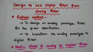
Analog filters are critical elements in the design of communication systems, facilitating signal conditioning by selectively passing or blocking frequency components. This section discusses how analog filters are constructed using resistors (R), capacitors (C), inductors (L), and operational amplifiers (Op-Amps). Examples such as the RC Low-Pass Filter illustrate basic filter functionality, which allows low-frequency signals to pass while attenuating higher frequencies. The active filter types, particularly those based on Op-Amps, enable gain amplification and precise control over cutoff frequencies, making them invaluable in various applications.
Key Parameters of Analog Filters
- Cutoff Frequency (fc): The frequency at which the filter begins to attenuate the input signal signals significantly.
- Gain: Represents the amplification in the passband, fundamentally influencing the filter's output.
- Bandwidth: Refers to the range of frequencies that are allowed to pass in the band filters, crucial for determining the filter's effectiveness in practical situations.
Youtube Videos
Audio Book
Dive deep into the subject with an immersive audiobook experience.
Components Used in Analog Filter Design
Chapter 1 of 3
🔒 Unlock Audio Chapter
Sign up and enroll to access the full audio experience
Chapter Content
● Built using resistors (R), capacitors (C), inductors (L), and operational amplifiers (Op-Amps).
Detailed Explanation
Analog filters are constructed using various electronic components. Resistors (R) limit the flow of electrical current, capacitors (C) store and release electrical energy, inductors (L) oppose changes in current, and operational amplifiers (Op-Amps) amplify signals. Together, these components can be configured in different ways to create various types of filters that allow certain frequencies to pass while blocking others.
Examples & Analogies
Think of these components like ingredients in a recipe. Just like you combine certain ingredients to create a dish (e.g., flour, sugar, and eggs for a cake), you combine resistors, capacitors, and inductors to create a filter that behaves in a specific way, allowing your favorite frequencies to 'taste' good while ignoring the 'bad' frequencies.
Examples of Analog Filters
Chapter 2 of 3
🔒 Unlock Audio Chapter
Sign up and enroll to access the full audio experience
Chapter Content
● Examples:
○ RC Low-Pass Filter: Simple filter that allows low-frequency signals.
○ Op-Amp Based Active Filters: Provide gain and precise control of cutoff frequencies.
Detailed Explanation
Two common examples of analog filters are the RC Low-Pass Filter and Op-Amp Based Active Filters. An RC Low-Pass Filter is straightforward; it allows low-frequency signals to pass through while attenuating higher frequencies. On the other hand, Op-Amp Based Active Filters not only filter signals but also amplify them, providing gain and allowing for precise control over the frequencies that are allowed through based on the design.
Examples & Analogies
Imagine you're at a concert with a loud band (high frequencies) and a small piano (low frequencies). An RC Low-Pass Filter is like a friend who helps you focus only on the piano music you like while cancelling out the band. Op-Amp Based Active Filters would be like having a concert sound engineer who can adjust the volume of the piano and band separately, ensuring you hear the right mix of sounds at the right loudness.
Key Parameters of Analog Filters
Chapter 3 of 3
🔒 Unlock Audio Chapter
Sign up and enroll to access the full audio experience
Chapter Content
Key Parameters:
● Cutoff Frequency (fc): Frequency at which filter begins to attenuate.
● Gain: Amplification of the signal in the passband.
● Bandwidth: Range of frequencies passed in band filters.
Detailed Explanation
When designing analog filters, it's essential to understand key parameters like Cutoff Frequency, Gain, and Bandwidth. The Cutoff Frequency (fc) is the point where the filter begins to reduce signal strength, meaning signals above or below this frequency will be attenuated. Gain refers to how much the filter can amplify a signal within its passband, while Bandwidth denotes the range of frequencies that the filter allows through, particularly important in band-pass filters that have specific bands of interest.
Examples & Analogies
Imagine you're tuning a radio to your favorite station. The Cutoff Frequency is like the point where the music starts to get clearer, and the interference (noise) starts to go down. The Gain is how much louder your chosen station sounds compared to the static around it, making it easier to enjoy the music. Bandwidth would be the range of stations you can hear clearly without interference, like a section of the radio dial where your favorite genre plays.
Key Concepts
-
Analog Filters: Circuits for signal conditioning using physical components.
-
Cutoff Frequency: The point of frequency attenuation in a filter.
-
Operational Amplifiers: Key components for building active filters.
Examples & Applications
An RC low-pass filter that smooths audio signals by removing high-frequency noise.
An active filter configuration using Op-Amps to create precisely controlled high-pass filters.
Memory Aids
Interactive tools to help you remember key concepts
Rhymes
For every good filter, remember the key, Low frequencies pass, while high ones flee.
Stories
Imagine a town (signal) where only certain cars (frequencies) can drive on a specific road (filter). The cutoff is the sign that says which cars can enter—only those under a certain speed.
Memory Tools
Use GAP to remember: Gain, Amplification, Precision are the advantages of Op-Amps in filters.
Acronyms
For cutoff frequencies remember
**C-RES** = Capacitors and RESistors influence the filter's Cutoff.
Flash Cards
Glossary
- Cutoff Frequency (fc)
The frequency at which a filter begins to attenuate the input signal.
- Gain
The amount of amplification of the signal within the filter's passband.
- Bandwidth
The range of frequencies that the filter allows to pass.
- Operational Amplifier (OpAmp)
A high-gain voltage amplifier with differential inputs and typically a single-ended output.
Reference links
Supplementary resources to enhance your learning experience.