
Introduction to Analog Circuits and Network Theory
Interactive Audio Lesson
Listen to a student-teacher conversation explaining the topic in a relatable way.
Fundamentals of Analog Signals
🔒 Unlock Audio Lesson
Sign up and enroll to listen to this audio lesson

Let's begin with the fundamentals of analog signals. What are analog signals?

They are signals that vary continuously over time!
Correct! They are continuous-time signals. Can anyone name a few key parameters of these signals?

They include amplitude, frequency, and phase!
Excellent! Remember, amplitude measures the strength, frequency indicates how fast it oscillates, and phase describes the position of the signal. Can anyone give an example of an analog signal?

Audio signals?
Right! Audio signals typically range from 20 Hz to 20 kHz. Great job, everyone! To summarize, analog signals are vital since they represent real-world phenomena in a continuous form.
Basic Circuit Elements
🔒 Unlock Audio Lesson
Sign up and enroll to listen to this audio lesson

Now, let's dive into basic circuit elements. What are passive components?

Components that do not produce power, like resistors and capacitors!
Exactly! Resistors, capacitors, and inductors fall under this category. Can anyone explain the I-V relationship of a resistor?
Yes! According to Ohm’s Law, V = IR.
Great! Now, what about active components like diodes and transistors?
They can amplify current or switch electronic signals!
Well done! Each component has its unique equations. Understanding these relationships is key to mastering circuit design.
Network Theorems
🔒 Unlock Audio Lesson
Sign up and enroll to listen to this audio lesson
Next, let's look at circuit analysis and start with Kirchhoff’s Laws. What does KCL state?
The sum of currents entering a node is zero!
Correct! And KVL states that the sum of the voltage around a closed loop is also zero. Now, how do Thévenin and Norton equivalents help us?
They simplify complex circuits into more manageable forms!
Exactly! Simplifying circuits makes it easier to analyze. Let's practice using these theorems in some examples?
Frequency Domain Analysis
🔒 Unlock Audio Lesson
Sign up and enroll to listen to this audio lesson
Moving on to frequency domain analysis. What is a transfer function, and why do we use it?
It describes the relationship between output and input signals in the frequency domain!
Exactly! And can anyone tell me the significance of a Bode plot?
It helps visualize how frequency affects the amplitude and phase of a system!
Spot on! Bode plots are essential for understanding system behavior at different frequencies. Let’s look at how to create them.
Practical Analog Circuits
🔒 Unlock Audio Lesson
Sign up and enroll to listen to this audio lesson
Lastly, let’s apply our understanding by discussing practical analog circuits. What is a voltage divider?
It's a simple circuit that outputs a voltage that is a fraction of the input voltage!
Correct! The formula for a voltage divider is Vout = Vin * (R2 / (R1 + R2)). Now, who can explain how an RC filter works?
It either passes or blocks certain frequencies from the input based on the RC time constant!
Excellent! Understanding these circuits is necessary for designing effective electronic systems.
Introduction & Overview
Read summaries of the section's main ideas at different levels of detail.
Quick Overview
Standard
The section provides a comprehensive overview of the fundamentals of analog circuits and network theory. It covers definitions and key parameters of analog signals, the components used in circuits, essential circuit theorems like Kirchhoff's, and introduces common filters and practical applications such as RC circuits.
Detailed
Detailed Summary
This section lays the foundational concepts of analog circuits and network theory. It begins with the fundamentals of analog signals, which are continuous-time signals that vary smoothly over time. Key parameters of these signals include amplitude, frequency, and phase, with real-world examples such as audio signals and sensor outputs.
Moving on to circuit elements, the section describes both passive components like resistors, capacitors, and inductors as well as active components like diodes and transistors. The importance of these components is highlighted through their mathematical relationships and energy behaviors.
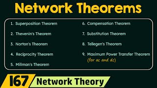
The section further discusses essential network theorems like Kirchhoff’s Laws for current and voltage conservation, and methods for simplifying circuit analysis using Thévenin and Norton equivalents. The superposition principle is also introduced as a crucial tool for analyzing linear systems.
Additionally, the section covers frequency domain analysis, including transfer functions and Bode plots, which are vital in understanding circuit behavior in AC analysis. This segues into practical applications of analog circuits, particularly voltage dividers and RC filters.
Lastly, a lab experiment is presented to help students characterize an RC circuit, culminating in a hands-on approach to apply theory to practical scenarios. Overall, this section emphasizes that analog circuits form the backbone of many electronic systems by processing continuous signals.
Youtube Videos


Audio Book
Dive deep into the subject with an immersive audiobook experience.
Fundamentals of Analog Signals
Chapter 1 of 5
🔒 Unlock Audio Chapter
Sign up and enroll to access the full audio experience
Chapter Content
1.1 Fundamentals of Analog Signals
- Definition:
- Continuous-time signals that vary smoothly over time (vs. discrete digital signals).
- Key Parameters:
- Amplitude (V, I)
- Frequency (Hz)
- Phase (θ)
- Examples:
- Audio signals (20Hz–20kHz)
- Sensor outputs (e.g., temperature, pressure)
Detailed Explanation
Analog signals are continuous signals that change smoothly over time. This is different from digital signals, which are discrete (they jump from one state to another). The three key parameters of analog signals are amplitude, frequency, and phase. Amplitude represents the strength or value of the signal, usually measured in volts (V) for voltage signals or amperes (A) for current signals. Frequency, measured in Hertz (Hz), indicates how many times the signal varies in one second. Phase, measured in degrees (θ), shows the position of the waveform in relation to time. Examples of analog signals include audio signals in the frequency range of 20 Hz to 20 kHz and outputs from various sensors like temperature or pressure sensors.
Examples & Analogies
Think of an analog signal like a dimmer switch for lights. As you turn the switch, the brightness of the light smoothly increases or decreases. This is like an analog signal changing its amplitude smoothly over time, as opposed to just turning the light on or off quickly, which would be like a digital signal.
Basic Circuit Elements
Chapter 2 of 5
🔒 Unlock Audio Chapter
Sign up and enroll to access the full audio experience
Chapter Content
1.2 Basic Circuit Elements
1.2.1 Passive Components
| Component | Symbol | I-V Relationship | Energy Behavior |
|---|---|---|---|
| Resistor (R) | ⏚ | V = IR (Ohm’s Law) | Dissipative |
| Capacitor (C) | ⏛ | I = C(dV/dt) | Energy storage (E=½CV²) |
| Inductor (L) | ⏜ | V = L(dI/dt) | Energy storage (E=½LI²) |
| #### 1.2.2 Active Components | |||
| - Diodes: | |||
| - Shockley equation: \( I = I_0(e^{V/nV_T} - 1) \) | |||
| - Transistors (BJT/FET): | |||
| - BJT: \( I_C = βI_B \) | |||
| - MOSFET: \( I_D = μ_nC_{ox}(W/L)(V_{GS}-V_{th})^2 \) |
Detailed Explanation
Basic circuit elements can be classified into passive and active components. Passive components include resistors, capacitors, and inductors. Resistors limit the flow of current and follow Ohm’s Law, which relates voltage (V), current (I), and resistance (R). Capacitors store energy in an electric field and charge and discharge based on the change in voltage over time, while inductors store energy in a magnetic field as current changes. Active components, like diodes and transistors, can control current flow and have their own behavior governed by specific equations, such as the Shockley equation for diodes and the respective equations for BJTs and MOSFETs.
Examples & Analogies
You can think of a resistor like a narrow pipe in a water system. It restricts how much water (current) can flow through, just like a resistor restricts electrical current. Capacitors and inductors are like storage tanks—capacitors store water temporarily and release it when needed, while inductors are akin to water wheels where energy from flowing water can be stored as rotational energy.
Network Theorems
Chapter 3 of 5
🔒 Unlock Audio Chapter
Sign up and enroll to access the full audio experience
Chapter Content
1.3 Network Theorems
1.3.1 Kirchhoff’s Laws
- KCL: \( \sum I_{node} = 0 \) (Current conservation)
- KVL: \( \sum V_{loop} = 0 \) (Energy conservation)
1.3.2 Thévenin/Norton Equivalents
| Theorem | Equivalent Circuit | Formula |
|---|---|---|
| Thévenin | V(cid:0)(cid:0) + R(cid:0)(cid:0) series | V(cid:0)(cid:0) = Open-circuit voltage |
| Norton | I(cid:0) + R(cid:0) parallel | I(cid:0) = Short-circuit current |
| #### 1.3.3 Superposition Principle | ||
| - For linear systems: Response = Σ(Individual source responses). |
Detailed Explanation
Network theorems are fundamental principles for analyzing electrical circuits. Kirchhoff’s Laws consist of two main rules: Kirchhoff's Current Law (KCL) states that the total current entering a junction must equal the total current leaving that junction, promoting the concept of current conservation. Kirchhoff's Voltage Law (KVL) states that the total voltage around a closed loop in a circuit must equal zero, ensuring energy conservation. Thévenin and Norton’s theorems allow us to simplify complex circuits into easier equivalent circuits: Thévenin used for voltage sources in series with a resistance, and Norton used for current sources in parallel. Lastly, the Superposition Principle helps in analyzing circuits with multiple sources by allowing you to analyze one source at a time and then combine the effects.
Examples & Analogies
Imagine a large city water system: KCL is akin to ensuring that the total amount of water entering a water reservoir equals the amount of water leaving; if more is entering, the reservoir will overflow. KVL is like making sure that the amount of pressure provided by different pumps in a circuit maintains a balance so that water flows correctly. Thévenin and Norton equivalents are like converting a complicated network of pipes and pumps into a single pipe with a consistent flow rate and pressure.
Frequency Domain Analysis
Chapter 4 of 5
🔒 Unlock Audio Chapter
Sign up and enroll to access the full audio experience
Chapter Content
1.4 Frequency Domain Analysis
1.4.1 Transfer Functions
- \( H(s) = \frac{V_{out}(s)}{V_{in}(s)} \), where \( s = jω \)
- Example: RC low-pass filter:
\[
H(s) = \frac{1}{1 + sRC}
\]
1.4.2 Bode Plots
- Magnitude (dB): \( 20\log_{10}|H(jω)| \)
- Phase: \( \angle H(jω) \)
- Corner Frequency: \( ω_c = \frac{1}{RC} \)
Detailed Explanation
Frequency domain analysis looks at how circuits respond to different frequencies. Transfer functions express the relationship between input and output signals, which helps to understand how a circuit modifies signals. The example provided is the transfer function for an RC low-pass filter, which allows low-frequency signals to pass while attenuating high-frequency signals. Bode plots are graphical representations showing both the magnitude (in decibels) and phase response of a system across a range of frequencies, with the corner frequency indicating the point where the output begins to decrease significantly.
Examples & Analogies
Think of a music equalizer. The equalizer allows you to boost certain frequencies (like bass or treble) while cutting others. The transfer function describes how much of each frequency gets enhanced or reduced, while Bode plots help visualize those adjustments over a range of frequencies.
Practical Analog Circuits
Chapter 5 of 5
🔒 Unlock Audio Chapter
Sign up and enroll to access the full audio experience
Chapter Content
1.5 Practical Analog Circuits
1.5.1 Voltage Dividers
- \( V_{out} = V_{in} \times \frac{R_2}{R_1 + R_2} \)
1.5.2 RC Filters
| Filter Type | Transfer Function | Application |
|---|---|---|
| Low-pass | \( \frac{1}{1 + jωRC} \) | Noise reduction |
| High-pass | \( \frac{jωRC}{1 + jωRC} \) | AC coupling |
Detailed Explanation
Practical analog circuits employ basic principles to achieve specific functionalities. A voltage divider is a simple circuit configuration that allows you to scale down a voltage to a desired level based on the resistance values used. The formula shows how output voltage depends on two resistors. RC filters are circuits that allow certain frequencies to pass while blocking others. Low-pass filters reduce high-frequency noise, while high-pass filters enable AC signals to pass and block low-frequency components, such as DC offsets.
Examples & Analogies
A voltage divider can be thought of like a staircase where each level represents a different voltage, allowing a person (the voltage) to step down to the desired height (voltage). In terms of filters, consider a fine mesh sieve: a low-pass filter is like the sieve that allows smaller, finer particles (low frequencies) to pass while trapping larger chunks (high frequencies), whereas a high-pass filter lets fine particles (high frequencies) through while holding back larger items (low frequencies).
Key Concepts
-
Analog Signals: Continuous-time representations of real-world phenomena.
-
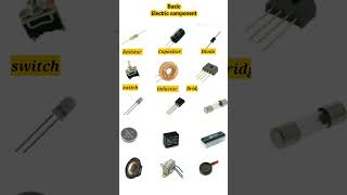
Passive Components: Elements like resistors, capacitors, and inductors that do not produce energy.
-
Active Components: Devices such as diodes and transistors that can amplify or switch signals.
-
Kirchhoff’s Laws: Fundamental principles about current and voltage in electrical circuits.
-
Thévenin/Norton Equivalent: Methods for simplifying circuits into equivalent form based on resistance and voltage/current sources.
-
Transfer Function: A mathematical way to express an output's response in frequency domain.
Examples & Applications
An audio signal fluctuating between voltages representing sound waves.
An RC low-pass filter reducing high-frequency noise in a signal.
Memory Aids
Interactive tools to help you remember key concepts
Rhymes
In circuits analog, signals flow, continuous as they go, with currents keeping on the beat, resistors help them not deplete.
Stories
Imagine a river (analog signal) flowing smoothly. Rocks (resistors) create ripples but don’t stop the flow, while bridges (capacitors) store some water for when it’s low.
Memory Tools
Remember the formula for voltage divider: 'V out = V in times R2 over R1 plus R2.' (V = IR is also a 'V' to remember.)
Acronyms
Use 'CRISP' for Circuit Elements
Capacitors
Resistors
Inductors
Sources
Passive.
Flash Cards
Glossary
- Analog Signals
Continuous-time signals that vary smoothly over time.
- Resistor
A passive component that resists the flow of electric current, defined by Ohm's law.
- Capacitor
A passive component that stores energy in an electric field.
- Inductor
A passive component that stores energy in a magnetic field.
- Diode
An active component that allows current to flow in one direction only.
- Transistor
An active component used to amplify or switch electronic signals.
- Kirchhoff's Current Law (KCL)
The total current entering a junction equals the total current leaving the junction.
- Kirchhoff's Voltage Law (KVL)
The sum of the electrical potential differences (voltage) around any closed loop in a circuit is zero.
- Thévenin's Theorem
Any linear electrical network can be replaced by an equivalent circuit consisting of a single voltage source and a series resistor.
- Norton’s Theorem
Any linear electrical network can be replaced by an equivalent circuit consisting of a single current source and a parallel resistor.
- Transfer Function
A mathematical representation of the relationship between the output and input of a system in the frequency domain.
Reference links
Supplementary resources to enhance your learning experience.