
Transfer Function Analysis
Interactive Audio Lesson
Listen to a student-teacher conversation explaining the topic in a relatable way.
Voltage Transfer Function
🔒 Unlock Audio Lesson
Sign up and enroll to listen to this audio lesson

Today, we'll begin with the concept of voltage transfer function, denoted as T_V. Can anyone tell me what a transfer function represents?

Is it the relationship between output and input voltage?
Exactly! The formula is T_V(s) = V_2(s)/V_1(s). Can someone give me an example of where we might use this?

How about in an RC low-pass filter?
Great thinking! For an RC low-pass filter, T_V(s) is given by T_V(s) = 1/(1 + sRC). Remember: R for resistance, C for capacitance. Can anyone summarize what the 's' represents here?

Oh, it represents the complex frequency variable in Laplace transforms, right?
Correct! And it helps in analyzing the filter's frequency response.
Current Transfer Function
🔒 Unlock Audio Lesson
Sign up and enroll to listen to this audio lesson

Now, let’s discuss the current transfer function, T_I. Who can remind us how it is defined?

T_I(s) = I_2(s) / I_1(s), right?
Exactly, well done! Why do you think analyzing current transfer is as important as voltage transfer?
Because it can help us understand how the circuit behaves in terms of current flow?
Yes, very important for circuit design! The interaction between input and output currents can reveal stability and efficiency issues.
So both voltage and current functions help us analyze different aspects of the network!
Exactly! Understanding both provides a comprehensive view of network behavior.
Introduction & Overview
Read summaries of the section's main ideas at different levels of detail.
Quick Overview
Standard
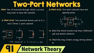
Transfer Function Analysis is a crucial part of understanding two-port networks, providing insight into the behavior of such systems. This section introduces the voltage transfer function, T_V(s), and the current transfer function, T_I(s), using examples such as the RC low-pass filter.
Detailed
Transfer Function Analysis
This section delves into the Transfer Function Analysis within two-port networks, outlining how voltage and current transfer functions define the relationship between input and output signals in the frequency domain.
Voltage Transfer Function (T_V)
The voltage transfer function is represented as:
$$ T_V(s) = \frac{V_2(s)}{V_1(s)} $$
where $V_2(s)$ is the output voltage and $V_1(s)$ is the input voltage. A pertinent example is the RC low-pass filter, given by the formula:
$$ T_V(s) = \frac{1}{1 + sRC} $$
This demonstrates how the output voltage is influenced by the circuit parameters of resistance (R) and capacitance (C).
Current Transfer Function (T_I)
The current transfer function is similarly defined as:
$$ T_I(s) = \frac{I_2(s)}{I_1(s)} $$
Emphasizing the relationship between output current $I_2(s)$ and input current $I_1(s)$. These transfer functions are essential for analyzing the behavior of two-port networks across various applications in electrical engineering.
Youtube Videos


Audio Book
Dive deep into the subject with an immersive audiobook experience.
Voltage Transfer Function
Chapter 1 of 2
🔒 Unlock Audio Chapter
Sign up and enroll to access the full audio experience
Chapter Content
9.2.1 Voltage Transfer Function (TV)
\[T_V(s) = \frac{V_2(s)}{V_1(s)} \quad \text{(Output/Input Voltage)}\]
- Example: RC Low-Pass Filter
\[T_V(s) = \frac{1}{1 + sRC}\]
Detailed Explanation
The voltage transfer function, denoted as T_V(s), represents the ratio of the output voltage (V_2) to the input voltage (V_1) in a system, which indicates how much of the input voltage is transferred to the output. In this context, it transforms the time domain signals into the frequency domain using the Laplace variable 's'. For an RC low-pass filter, the transfer function simplifies to T_V(s) = 1/(1+sRC), where 'R' is resistance and 'C' is capacitance. This expression shows that the output voltage decreases as frequency increases, indicating that higher frequencies are attenuated by the filter.
Examples & Analogies
Think of the RC low-pass filter as a sieve that allows water (representing low-frequency signals) to pass through while blocking larger debris (representing high-frequency signals). As you increase the flow (frequency), the sieve becomes less effective at allowing larger particles to pass through, thus illustrating how the voltage transfer function operates.
Current Transfer Function
Chapter 2 of 2
🔒 Unlock Audio Chapter
Sign up and enroll to access the full audio experience
Chapter Content
9.2.2 Current Transfer Function (TI)
\[T_I(s) = \frac{I_2(s)}{I_1(s)} \quad \text{(Output/Input Current)}\]
Detailed Explanation
The current transfer function, T_I(s), describes the ratio of the output current (I_2) to the input current (I_1) within a network. This indicates how effectively the current from the input is being converted to output, similar to the voltage transfer function but focusing specifically on current flow. T_I(s) helps understand how current behaves in different frequency ranges, particularly in circuits designed to amplify or attenuate signals.
Examples & Analogies
Imagine a busy road where cars (representing input current) enter a toll booth (representing the network). The toll booth allows some cars to pass through while stopping others, similar to how a circuit may allow certain frequencies of current to pass while blocking others. The ratio of cars entering versus cars exiting serves as a metaphor for the current transfer function.
Key Concepts
-
Voltage Transfer Function (T_V): Defines the relationship between output voltage and input voltage.
-
Current Transfer Function (T_I): Represents the relationship between output current and input current.
-
RC Low-Pass Filter: A practical realization of transfer functions, illustrating frequency response.
Examples & Applications
RC Low-Pass Filter Example: T_V(s) = 1/(1 + sRC)
Current Transfer Function Example: T_I(s) = I_2(s)/I_1(s)
Memory Aids
Interactive tools to help you remember key concepts
Rhymes
For V and I, the T function's fine, output over input is what you'll find.
Stories
The stronger the pressure (input), the more water flows out (output) illustrating the transfer functions.
Memory Tools
VIP for Transfer Functions: 'V' for Voltage, 'I' for Current, and 'P' for Power in transfer analysis.
Acronyms
Remember 'TIV' - T for Transfer, I for Input, and V for Output in understanding circuits.
Flash Cards
Glossary
- Voltage Transfer Function (T_V)
The ratio of the output voltage to the input voltage in a two-port network.
- Current Transfer Function (T_I)
The ratio of the output current to the input current in a two-port network.
- RC LowPass Filter
A circuit that allows low-frequency signals to pass while attenuating higher frequencies.
Reference links
Supplementary resources to enhance your learning experience.