
Maximizing Gain and Output Swing
Enroll to start learning
You’ve not yet enrolled in this course. Please enroll for free to listen to audio lessons, classroom podcasts and take practice test.
Interactive Audio Lesson
Listen to a student-teacher conversation explaining the topic in a relatable way.
Maximizing Gain
🔒 Unlock Audio Lesson
Sign up and enroll to listen to this audio lesson

Today, we will discuss how we can maximize gain in Common Emitter Amplifiers. What do you think gain refers to in our context?

I think gain measures how much an amplifier boosts the input signal.
Exactly! The voltage gain of an amplifier is a ratio of output voltage to input voltage. To optimize this, we need to consider factors such as supply voltage, resistor values, and thermal voltage. Can you recall the maximum gain we can achieve from a single stage?

I remember it being around 230?
Correct, but if we want higher gain, we might need to cascade multiple stages. Does anyone know what cascading means?

It's connecting multiple amplifiers together to increase total gain.
Right! Remember the acronym 'SAGE' — S for Supply, A for Amplify, G for Gain, E for Efficiency. Let’s summarize here: maximizing gain involves careful component selection and understanding how to connect stages.
Output Swing
🔒 Unlock Audio Lesson
Sign up and enroll to listen to this audio lesson

Now let’s talk about maximizing output swing. Why do you think output swing is important?

It determines the range within which the amplifier can operate without distortion.
Exactly! The output swing can be influenced by the supply voltage. Can anyone tell me how we can ensure we're achieving maximum swing without distortion?
By properly biasing the amplifier?
Right! Ensuring that the amplifier is correctly biased allows for maximum output swing. If we set the output around the mid-point of V_CC, we maximize the dynamic range. Always remember, a common guideline is to keep the swing close to the limits of your power supply while preventing clipping!
Effect of Feedback Resistors
🔒 Unlock Audio Lesson
Sign up and enroll to listen to this audio lesson
Let’s dive into feedback resistors. How do feedback resistors affect gain?
They can reduce gain if not designed properly.
Absolutely! When designing an amplifier with lower gain, we can bypass some resistors selectively. What do you think is the reason we would want to bypass a resistor?
To maintain gain while keeping bias point stability?
Exactly! It allows us to manage the gain while preventing large fluctuations due to variations in beta. Our key takeaway should be that managing feedback resistors is crucial for the overall performance of our circuits.
Cascading Stages for Higher Gain
🔒 Unlock Audio Lesson
Sign up and enroll to listen to this audio lesson
Last, we’ll look into cascading amplifier stages for increased gain. Why would we do this instead of relying on one amplifier?
To achieve a gain greater than the single-stage limit.
Right! By cascading, we can multiply the gains of each stage. However, can you think of a potential drawback?
If the input resistance of the next stage is too low, it could load down the previous stage.
Exactly! This inter-stage loading can affect the overall gain, so we have to select our components carefully. Remember the guideline for cascading: the input resistance of the next stage should ideally be much greater than the output resistance of the previous stage. Let’s summarize today’s session on cascading as a strategy for achieving higher gains effectively!
Introduction & Overview
Read summaries of the section's main ideas at different levels of detail.
Quick Overview
Standard
The section elaborates on the importance of adjusting design parameters to optimize gain and output swing in CE Amplifiers. It highlights strategies to achieve either higher or lower gain and provides insights on managing the effects of feedback resistors and cascading amplifiers for better performance.
Detailed
Maximizing Gain and Output Swing
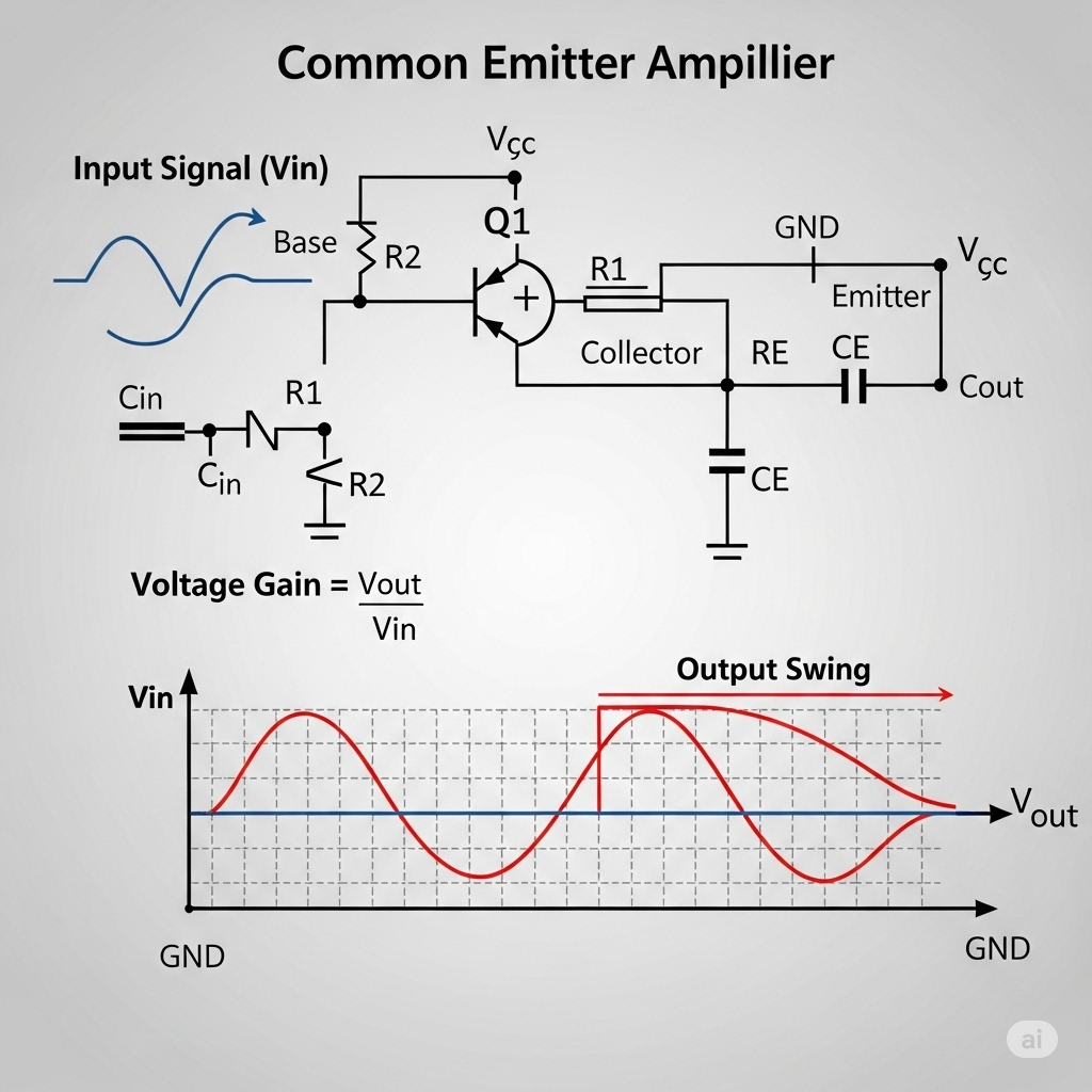
In this section of the lecture on Common Emitter (CE) Amplifiers, we focus on strategies to maximize both voltage gain and output swing while maintaining power dissipation. The primary objective here is to reach a gain that is optimal for the circuit application without exceeding predetermined limits, such as a maximum voltage gain from the circuit's design. The expression for voltage gain is emphasized, noting its dependence on parameters like the power supply voltage (V_CC) and thermal equivalent voltage.
The necessity of designing amplifiers for lower gain is addressed by explaining the trade-offs involved in modifying design components such as feedback resistors (R_E). Partial bypassing of emitter resistors is proposed as a method for maintaining bias point stability while allowing for the desired voltage gain.
Furthermore, for applications requiring higher gain than achievable through a single-stage amplifier, methods such as cascading multiple amplifier stages are outlined. Both aspects of increasing and reducing gain are analyzed through circuit model examples including the impact on input and output resistance, demonstrating the importance of tailoring the design for specific application needs. This comprehensive exploration lets engineers effectively manipulate amplifier characteristics to meet operational requirements.
Youtube Videos

Audio Book
Dive deep into the subject with an immersive audiobook experience.
Objective of Maximizing Gain
Chapter 1 of 5
🔒 Unlock Audio Chapter
Sign up and enroll to access the full audio experience
Chapter Content
So, far we have discussed about the design guidelines where or mean objective there is to maximize the gain, voltage gain right. And, also the output swing we like to maximize and the power dissipation probably it is given value.
Detailed Explanation
The primary goal when designing a common emitter (CE) amplifier is to maximize two crucial factors: gain and output swing. Gain refers to how much the amplifier increases the input signal's voltage, while output swing indicates the range of voltages the amplifier can produce without clipping. High gain is essential for effectively amplifying weak signals, and a wide output swing ensures that the amplifier can process varying signal levels without distortion.
Examples & Analogies
Think of an amplifier like a microphone system at a concert. The goal is to not only make the singer's voice louder (maximizing gain) but also to ensure that the loudest notes don't cause distortion (maximizing output swing). You want the microphone to capture all nuances of the voice while preventing any distortion during those powerful high notes.
Understanding Output Swing and Gain Relationships
Chapter 2 of 5
🔒 Unlock Audio Chapter
Sign up and enroll to access the full audio experience
Chapter Content
This maximization of output swing of course, it is decided by the V predominantly. So, likewise maximization of the gain is also it is decided by this V and thermal equivalent voltage and of course, the output swing.
Detailed Explanation
The output swing is mainly influenced by the supply voltage (V_CC). A higher supply voltage typically allows for a greater output swing, meaning the amplifier can output larger signal peaks without distortion. Similarly, the gain of the amplifier is also tied to the voltage levels involved in the circuit, such as the thermal equivalent voltage, which impacts how effectively the components function together. Thus, both output swing and gain are interdependent on the circuit's voltage supply.
Examples & Analogies
Consider a water faucet. If you have a higher water pressure (akin to higher voltage), you can get a lot of water out (output swing). But if the faucet's opening is narrow (low gain), you won't get much water, even if the pressure is high. You need both adequate pressure and a wide opening to maximize water flow, just as you need the right voltage levels in an amplifier for optimal gain and swing.
Designing for Higher or Lower Gain Requirements
Chapter 3 of 5
🔒 Unlock Audio Chapter
Sign up and enroll to access the full audio experience
Chapter Content
In case if we are looking for an amplifier having again, which is less than this limit, then how do you design? And, of course, having higher swing it is always better.
Detailed Explanation
When designing an amplifier that requires a lower gain than the maximum threshold, adjustments are needed to ensure stability and performance. Designers can alter resistor values or adjust configuration elements in the circuit. This flexibility allows for tuning the gain to match both the desired output and the inherent properties of the circuit components.
Examples & Analogies
Imagine tuning a guitar. If the guitar strings are too tight (too much gain), the sound can distort. But if they are too loose (too low gain), you won't hear any music. The key is in finding the right balance of tension (gain) to produce beautiful music (desired output) without distortion. Adjusting the strings allows you to set the perfect tone for any song.
Using Resistors to Control Gain and Stability
Chapter 4 of 5
🔒 Unlock Audio Chapter
Sign up and enroll to access the full audio experience
Chapter Content
Instead of completely ignoring the C or instead of completely bypassing this R, what you can do we can partially bypass this resistor?
Detailed Explanation
To manage gain and ensure the amplifier remains stable against variations in input parameters, designers can choose to partially bypass certain resistors in the circuit. This approach means that while some current can flow through the bypass capacitor (C), which helps with gain, other current still flows through the resistor (R), which is essential for bias point stability. This balance allows for achieving the desired gain while maintaining the circuit's overall stability.
Examples & Analogies
Think of using a water filter. If you remove the filter entirely, the water may flow freely but can carry impurities (loss of stability). If you keep the filter completely intact, the water flow is restricted (too much stability). But if you cut a small section out of the filter, it allows for good water flow while still cleaning out impurities. This is the balance that partial bypassing aims to achieve in an amplifier.
Cascading Amplifiers for Higher Gain
Chapter 5 of 5
🔒 Unlock Audio Chapter
Sign up and enroll to access the full audio experience
Chapter Content
So, the next thing is that in case if we are looking for a circuit having this gain, which is higher than the limit of the maximum gain we are achieving from single stage for a given value of V.
Detailed Explanation
If the design requires a gain exceeding the single-stage limits, cascading multiple amplifier stages can be an effective solution. In this process, the output of one amplifier feeds into the next, allowing the total gain to be a product of the individual gains. This method is particularly useful when needing significantly higher amplification without compromising the characteristics of each stage.
Examples & Analogies
Consider a relay race. Each runner (amplifier) takes over from the previous one to cover a longer distance (higher gain) without exhausting any one runner too much (stage limits). Just as each runner boosts the overall distance reached, cascading amplifiers work together to achieve the desired level of amplification, efficiently sharing the task.
Key Concepts
-
Voltage Gain: Important for assessing how much an amplifier boosts signals.
-
Output Swing: Critical for determining the operational range without clipping.
-
Power Dissipation: The maximum power that can be safely dissipated in the amplifier without damage.
Examples & Applications
If designing a CE amplifier for a specific application where a gain of 20 is needed, you would calculate resistor values accordingly to maintain stability and avoid bias point fluctuations.
In a practical scenario, cascading two amplifiers with individual gains of 10 and 15, respectively, can yield a total gain of 150 if designed to avoid loading effects.
Memory Aids
Interactive tools to help you remember key concepts
Rhymes
To gain the best, bias with zest, keep the swing within the best!
Stories
Imagine a performer on stage (the amplifier) whose voice (the signal) can only reach so far (output swing). With the right setup (biasing), they give the best performance (maximized gain) without veering off-key (clipping).
Memory Tools
Remember 'SAGE' — Supply, Amplify, Gain, Efficiency for amplifiers!
Acronyms
GASP — Gain, Amplifier, Stability, Performance for designing CE amplifiers.
Flash Cards
Glossary
- Common Emitter Amplifier (CE Amplifier)
A type of bipolar junction transistor amplifier where the emitter is common to both the input and output.
- Gain
The ratio of the output voltage to the input voltage in an amplifier.
- Output Swing
The maximum voltage range the amplifier can output without distortion.
- Cascading
Connecting multiple amplifier stages in series to increase overall gain.
- Feedback Resistor
Resistors used to adjust the gain and stability of the amplifier circuit.
Reference links
Supplementary resources to enhance your learning experience.