
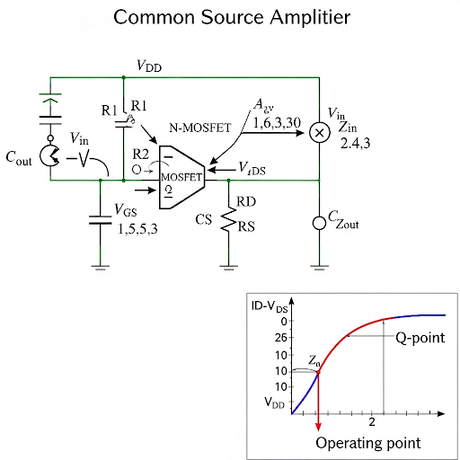
Common Source Amplifier (Contd.)
Enroll to start learning
You’ve not yet enrolled in this course. Please enroll for free to listen to audio lessons, classroom podcasts and take practice test.
Interactive Audio Lesson
Listen to a student-teacher conversation explaining the topic in a relatable way.
Introduction to Common Source Amplifier Design Guidelines
🔒 Unlock Audio Lesson
Sign up and enroll to listen to this audio lesson

Today we are going to discuss the design guidelines for common source amplifiers. Can anyone tell me why selecting the right component values is crucial?

It ensures that the amplifier operates correctly and maintains the desired gain.
Exactly! The correct selection of resistors helps to set the operating point and maximize the output signal swing. Let's outline the key steps involved in this process.

What do you mean by output signal swing?
The output swing refers to the range of the output voltage. It is essential for ensuring the amplifier can effectively amplify the input signal without distortion. We'll discuss how we can calculate this and adjust our resistor values accordingly.
Calculating Component Values
🔒 Unlock Audio Lesson
Sign up and enroll to listen to this audio lesson

Let's dive deeper into finding the values of R1 and R2 based on target current and operating voltage. If we want a drain current of 0.5 mA, how can we find VGS?

We can use the equation IDS = K × W/L × (VGS - VTH)^2.
Correct! So, if we know IDS, we can rearrange it to find VGS. Can anyone tell me which values we need to plug in?

We'll need K, W, L, and VTH, along with the supply voltage.
Right! Once we have VGS, the next step is to calculate the ratios of R1 and R2. How do we approach that?
By setting up the voltage divider equation based on the supply voltage.
Exactly!
Evaluating Amplifier Performance
🔒 Unlock Audio Lesson
Sign up and enroll to listen to this audio lesson
After we calculate R1 and R2, we need to check the performance of the amplifier. Can anyone name some key metrics we need to evaluate?
Output swing, gain, and input/output resistances.
Correct! The output swing should ideally allow for equal positive and negative excursions. How do we ensure this?
By placing the DC operating point at the midpoint between the supply voltage and the threshold voltage.
Exactly! Balancing it helps avoid clipping of the signal.
Introduction & Overview
Read summaries of the section's main ideas at different levels of detail.
Quick Overview
Standard
In this section, we explore the design guidelines for common source amplifiers, including the calculation of resistor values to ensure meaningful operation and signal swing. Through numerical examples, we detail the procedures for selecting bias resistors and capacitors while maintaining the transistor in the saturation region.
Detailed
The section continues the discussion on common source amplifiers by elaborating on the design guidelines necessary for constructing an effective amplifier circuit. Initially, we analyze the importance of the operating point and how both DC and AC parameters influence the selection of bias resistors (R1, R2) and the load resistor (RD). The aim is to achieve a balance in output signal swing while ensuring that the transistor remains in saturation during operation. We delve into specific numerical examples, illustrating how to derive the voltages and resistor ratios from given parameters, such as supply voltage and desired drain current. Consequently, common calculations for gain, input resistance, and output resistance are presented as part of the design evaluation, enabling an understanding of how changes in bias resistors can affect overall performance. The examples cement knowledge by demonstrating practical calculations that align with theoretical principles in analog electronic circuits.
Youtube Videos

Audio Book
Dive deep into the subject with an immersive audiobook experience.
Introduction to Design Guidelines
Chapter 1 of 6
🔒 Unlock Audio Chapter
Sign up and enroll to access the full audio experience
Chapter Content
Today we will be covering some of the design guidelines, how we have to select values of different components.
Detailed Explanation
In this section, the presenter introduces the topic of design guidelines focused on common source amplifiers. The aim is to help students understand the process of selecting appropriate component values like resistors and capacitors to achieve desired performance in the amplifier circuit.
Examples & Analogies
Think of building a bridge. Before you start constructing, you need to ensure you have the right materials and designs to withstand the elements and traffic. Similarly, in circuit design, selecting the right components ensures that the amplifier performs effectively.
Theoretical vs Numerical Analysis
Chapter 2 of 6
🔒 Unlock Audio Chapter
Sign up and enroll to access the full audio experience
Chapter Content
Today we are going to discuss the reverse process, namely in case the circuit is given to us and the circuit topology is given to us along with device parameters and the supply voltage is given to us. And, we need to find; we need to find the values of these resistors namely the bias resistors R1, R2, then RD.
Detailed Explanation
The speaker differentiates between theoretical and numerical analysis. Theoretical analysis involves understanding how to calculate gain and resistance based on given parameters, whereas numerical analysis focuses on determining values of resistors based on a pre-defined circuit configuration and performance requirements.
Examples & Analogies
Imagine you’re cooking a recipe. The theoretical part is knowing what ingredients you should use and their proportions, while the numerical analysis is measuring out exactly how much of each ingredient you actually need based on your recipe and serving size.
Selecting the Bias Resistors
Chapter 3 of 6
🔒 Unlock Audio Chapter
Sign up and enroll to access the full audio experience
Chapter Content
So, the main focus of today’s discussion is primarily to find rather to how to select the value of different bias components.
Detailed Explanation
This chunk discusses how to select the appropriate bias resistor values to ensure the common source amplifier operates effectively. Choosing the right values helps maintain the transistor in its intended region of operation, ensuring optimal signal swing and overall circuit functionality.
Examples & Analogies
Consider tuning a musical instrument; tuning it to the right pitch allows for a beautiful melody. Similarly, biasing the amplifier to the correct levels ensures it works smoothly and efficiently, improving sound clarity in audio applications.
Understanding DC Operating Points
Chapter 4 of 6
🔒 Unlock Audio Chapter
Sign up and enroll to access the full audio experience
Chapter Content
For meaningful operation a we want both the positive swing as well as the negative swing may be equal. And hence we like to keep the DC voltage at the drain such that we should be getting both positive side as well as the negative side, equal means the V_DS should be middle of these two voltages.
Detailed Explanation
This section explains the importance of setting the DC operating point at the midpoint between the upper and lower swing limits of the output voltage. A balanced operation allows the amplifier to achieve both positive and negative swings effectively, ensuring clear signal amplification.
Examples & Analogies
Think of balancing a seesaw. For it to work correctly, both sides should have equal weight. Similarly, in an amplifier, the DC operating point must be balanced to prevent distortion in the amplified signal.
Determining Resistor Values
Chapter 5 of 6
🔒 Unlock Audio Chapter
Sign up and enroll to access the full audio experience
Chapter Content
To obtain this 1 mA of current we need this V_GS should be 2 V... so that gives us the corresponding value of R1 and R2.
Detailed Explanation
The speaker illustrates how to determine the specific values of resistors R1 and R2 based on the desired gate-source voltage (V_GS) and target bias current. This exercise showcases the mathematical relationships used in circuit design to arrive at the required component values.
Examples & Analogies
Just like creating a budget for a project requires adjusting the amounts allocated to various expenses, in circuit design, we allocate specific resistor values to ensure that our amplifier has the desired current and voltage characteristics.
Gain Calculation and Performance Metrics
Chapter 6 of 6
🔒 Unlock Audio Chapter
Sign up and enroll to access the full audio experience
Chapter Content
The corresponding gain what we can get is gm × RD. In fact, we can write the expression of the gm in terms of I and (VGS − Vth).
Detailed Explanation
Finally, the speaker discusses how to calculate the voltage gain of the amplifier using the transconductance (g_m) and the drain resistor (R_D). This chunk emphasizes the importance of these parameters in assessing the performance of the amplifier design.
Examples & Analogies
Think of an amplifier's gain like the performance of a team sporting an event. The team's ability to score points (gain) comes from their preparation and skill level (g_m and R_D), impacting their success in a tournament.
Key Concepts
-
Component Values Selection: The importance of choosing appropriate resistor and capacitor values for an amplifier's optimal functioning.
-
Operating Point: The defined point of operation for an amplifier determines its performance and output swing.
-
Gain Calculation: Understanding how to calculate the gain based on the transistor's characteristics and circuit configuration.
Examples & Applications
Setting R1 and R2 for a given VGS from a 12V supply to achieve a target IDS of 0.5 mA.
Calculating the corresponding RD to maximize output swing based on the selected bias.
Memory Aids
Interactive tools to help you remember key concepts
Rhymes
In a common source amp, keep your gains in sight, Resistors guide the current, make the output right!
Stories
Imagine an engineer at a café adjusting coffee brewing time, just like they set up resistors for voltage in an amplifier, ensuring every drop is just right for that perfect cup!
Memory Tools
R.A.C.E - Resistors for Amplifier Current and Efficiency. Remember this to choose the right components!
Acronyms
D.C.G - Design for Current Gain. This helps remember that the focus of design is on achieving the desired gain.
Flash Cards
Glossary
- Common Source Amplifier
A type of amplifier where the input signal is applied to the gate terminal, and the output is taken from the drain terminal, commonly used for voltage amplification.
- Bias Resistor
Resistors used to set the DC operating point of the transistor in an amplifier circuit.
- Operating Point
The specific DC voltage and current values at which an amplifier is set to operate.
- Output Swing
The range of output voltage that the amplifier can produce without distortion.
- Drain Current (IDS)
The current flowing from the drain of the transistor, determined by the input voltage and transistor characteristics.
- Threshold Voltage (VTH)
The minimum gate-to-source voltage required to turn the transistor on.
- Voltage Divider
A simple circuit used to reduce voltage by distributing it among resistors.
Reference links
Supplementary resources to enhance your learning experience.