
Bias Resistor Selection
Enroll to start learning
You’ve not yet enrolled in this course. Please enroll for free to listen to audio lessons, classroom podcasts and take practice test.
Interactive Audio Lesson
Listen to a student-teacher conversation explaining the topic in a relatable way.
Introduction to Bias Resistors
🔒 Unlock Audio Lesson
Sign up and enroll to listen to this audio lesson

Welcome to our discussion on bias resistor selection for common source amplifiers! Can anyone explain the role of bias resistors in amplifiers?

They help set the DC operating point of the transistor, right?
Exactly! The bias resistors ensure the transistor stays in the saturation region, which is crucial for proper signal amplification. Let's remember this with the acronym 'BAS' - 'Bias, Amplify, Saturate.'

What happens if the transistor isn't biased correctly?
If the biasing is off, we may experience distortion or clipping in our output signal. Could someone tell me what key factors we need to consider when choosing these resistors?

Supply voltage and transistor parameters?
Correct! As we select the resistor values, we also need to ensure we achieve a good signal swing at the output. Let's summarize! Remember 'BAS' for Bias, Amplify, and Saturate, to keep our amplifier functioning optimally.
Calculating Resistor Values
🔒 Unlock Audio Lesson
Sign up and enroll to listen to this audio lesson

Continuing from our last session, let’s use a numerical example to dive into resistor calculations. If we select a target drain current of 0.5 mA, how can we find the required gate-source voltage?
Would we use the equation I_DS = K*(W/L)*(V_GS - V_th)^2?
Exactly! Applying this equation helps us determine the necessary gate-source voltage to achieve the desired drain current. What would our next step be?
We would need to calculate the corresponding resistor values using the supply voltage.
Yes! We manipulate V_GS and the supply voltage using the voltage divider rule to find the resistor values. Let's remember the 'Voltage Divider Rule' as 'VDR- Vector Design Ratio.'
Could you clarify how we derive the resistor values from the voltage drop?
Certainly! Once we have V_GS, we can determine what the ratios of R1 and R2 need to be to set this voltage. Let’s recap! 'VDR' = Voltage Divider Ratio is essential for our calculations.
Practical Design and Performance
🔒 Unlock Audio Lesson
Sign up and enroll to listen to this audio lesson
Now, let’s discuss how the bias resistor values we've calculated influence the amplifier's performance. What outcomes should we anticipate?

The output swing and gain, right?
Exactly! A well-chosen DC operating point maximizes output swing while ensuring gain is maintained. Can anyone remind me why we want equal positive and negative swing?
So the signal doesn’t clip on one side and stays symmetrical?
Very good! Remember this principle as 'Symmetry for Stability.' Finally, we always want to check our gain and input/output resistances after we select our resistor values.
Introduction & Overview
Read summaries of the section's main ideas at different levels of detail.
Quick Overview
Standard
In this section, important design guidelines for bias resistor selection in common source amplifiers are discussed, including how resistor values impact the DC operating point and the overall circuit performance, such as gain and output swing. Several numerical examples demonstrate the calculations necessary for optimal resistor selection.
Detailed
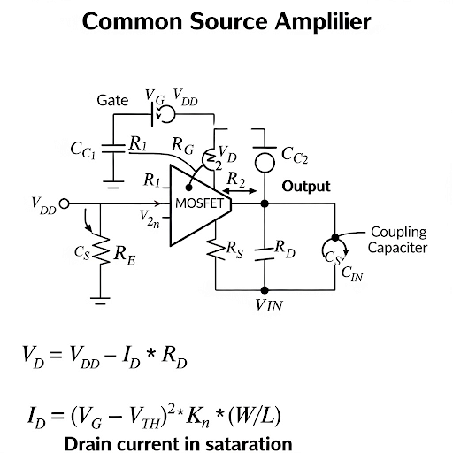
In this section, we delve into bias resistor selection for common source amplifiers, emphasizing design guidelines for achieving optimal performance. The section begins with an overview of circuit analysis, transitioning into how to select values for biasing resistors when given specific parameters, such as supply voltage and transistor characteristics. The primary concern is to ensure that the transistor remains in saturation while providing an ample signal swing at the output. Key calculations are presented, including determining the drain voltage and current, followed by deriving formulas for the necessary resistors. A series of numerical examples illustrate this methodology, enabling students to understand practical applications of their learning. Ultimately, this section stresses the importance of correctly selecting resistor values to optimize amplifier signal and performance, thereby preparing students for real-world circuit design challenges.
Youtube Videos

Audio Book
Dive deep into the subject with an immersive audiobook experience.
Understanding the Goal of Bias Resistor Selection
Chapter 1 of 7
🔒 Unlock Audio Chapter
Sign up and enroll to access the full audio experience
Chapter Content
The main focus of today’s discussion is primarily to find how to select the value of different bias components.
Detailed Explanation
This chunk introduces the critical objective of bias resistor selection. The bias resistors play a significant role in setting the operating point of the amplifier, ensuring it functions effectively within the desired parameters. Selecting the correct resistor values is crucial for achieving a good output signal swing.
Examples & Analogies
Think of bias resistors like the foundation of a building. Just as a building needs a solid foundation for stability, an amplifier requires well-chosen bias resistors for optimal performance.
Defining Circuit Parameters
Chapter 2 of 7
🔒 Unlock Audio Chapter
Sign up and enroll to access the full audio experience
Chapter Content
The circuit topology is given to us and the value of device parameters are provided. Additionally, the supply voltage is specified.
Detailed Explanation
In this chunk, we understand that certain parameters and components will be predefined, such as the circuit configuration and the device characteristics. With these values in hand, we can start the process of calculating the necessary resistor values that ensure the circuit operates correctly.
Examples & Analogies
Imagine you're planning a road trip. You need a map (the circuit topology) and a vehicle’s specs (device parameters) to decide the best route (resistor values). Without these, it’s hard to plan effectively.
Maintaining Appropriate Operating Region
Chapter 3 of 7
🔒 Unlock Audio Chapter
Sign up and enroll to access the full audio experience
Chapter Content
While keeping the circuit in an appropriate region of operation, namely the transistor should be in saturation region.
Detailed Explanation
Here, the importance of ensuring that the transistor operates in the saturation region is highlighted. This is crucial for the amplifier's function since being in saturation allows the transistor to amplify signals effectively without distortion. Additionally, it’s important to ensure the drain-to-source voltage (V_DS) supports signal swings.
Examples & Analogies
Think of the saturation region like a car's optimal speed range. Just as a car operates best within a specific speed for fuel efficiency, the transistor must operate in a certain 'speed' range (saturation) for optimal performance.
Calculating the DC Operating Point
Chapter 4 of 7
🔒 Unlock Audio Chapter
Sign up and enroll to access the full audio experience
Chapter Content
The output voltage should be kept such that we should be getting both positive side as well as the negative side, equal means the V_DS should be in the middle of two voltages.
Detailed Explanation
This section covers the importance of the DC operating point, specifically setting it so that the output can swing positively and negatively around it. The goal is to center the DC voltage in a way that maintains equal swing capability, maximizing output signal potential.
Examples & Analogies
Consider balancing a seesaw. For it to move evenly, you need to position the weight (DC voltage) in the center. If you shift it to one side, one end will drop (less swing), while the other will rise (more swing), causing imbalance.
Selecting Resistor Ratios
Chapter 5 of 7
🔒 Unlock Audio Chapter
Sign up and enroll to access the full audio experience
Chapter Content
Using the equation V_GS = V_th + ΔV, we can find the necessary resistor ratios to achieve the gate voltage needed.
Detailed Explanation
In this chunk, the relationship between gate-source voltage (V_GS), threshold voltage (V_th), and overdrive voltage (ΔV) comes into play. By understanding this relationship, we can derive the ratios of the resistors needed to set the appropriate bias points to obtain desired currents.
Examples & Analogies
Think of this like adjusting the proportions of ingredients in a recipe. Just as using the correct ratio of ingredients can lead to a successful dish, the right resistor ratios can ensure the amplifier performs optimally.
Final Calculations for Resistor Values
Chapter 6 of 7
🔒 Unlock Audio Chapter
Sign up and enroll to access the full audio experience
Chapter Content
To find absolute resistor values, the bias current is set as a certain percentage of the target current.
Detailed Explanation
Once the resistor ratios are established, we can calculate the actual resistor values by setting the bias current. This involves considering the overall current specifications and the supply voltage. This calculation helps in determining the resistance values that will satisfy the biasing conditions of the amplifier.
Examples & Analogies
Imagine budgeting for a project. You start with a total amount (supply voltage) and decide on a portion for various expenses (resistor values). Each choice you make impacts whether you stay within budget or overspend.
Performance Evaluation of the Design
Chapter 7 of 7
🔒 Unlock Audio Chapter
Sign up and enroll to access the full audio experience
Chapter Content
The output swing, gain, input resistance, and output resistance are discussed as key performance metrics.
Detailed Explanation
Finally, this segment covers how to evaluate the overall performance of the amplifier based on the previously calculated parameters. By assessing output swing, gain, and resistances, one can determine if the design meets the intended specifications and operational effectiveness.
Examples & Analogies
Just like assessing the performance of a new smartphone based on its features (battery life, speed, camera quality), evaluating these parameters helps determine if the amplifier will function well in practical applications.
Key Concepts
-
Bias Resistors: Essential for setting the DC operating point.
-
DC Operating Point: The point where the transistor functions optimally for signal amplification.
-
Output Swing: The maximum deviation of the output signal from the bias point.
-
Gain Calculation: Important for assessing how much the amplifier will amplify the input signal.
-
Voltage Divider Rule: A critical concept for resistor value calculation.
Examples & Applications
If a target drain current I_DS is set to 0.5 mA, the relevant formulas can find the necessary bias voltages to retain saturation.
Through careful selection of resistor values, the biasing ensures the amplifier achieves a gain of 11.
Memory Aids
Interactive tools to help you remember key concepts
Rhymes
Bias sets the point, to swing with delight, keep gain in view, for performance that's right.
Stories
Once an amplifier named Bessie learned how her resistors guided her to stay balanced, swinging freely in both directions, achieving gains that were a delight!
Memory Tools
Remember 'BAS' for Bias, Amplify, Saturate.
Acronyms
VDR - Voltage Divider Rule helps calculate resistor values.
Flash Cards
Glossary
- Bias Resistor
A resistor used to set the DC operating point of a transistor in an amplifier circuit.
- DC Operating Point
The steady-state point of operation for a transistor where it maintains proper function for AC signals.
- Saturation Region
The operating region of a transistor where it is fully 'on,' allowing maximum current flow.
- Gain
The ratio of the output signal to the input signal, indicating how much an amplifier increases the signal.
- Voltage Divider Rule
A simple rule to determine the voltage across components in a series circuit based on their resistances.
Reference links
Supplementary resources to enhance your learning experience.