
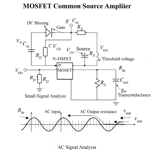
Circuit Description
Enroll to start learning
You’ve not yet enrolled in this course. Please enroll for free to listen to audio lessons, classroom podcasts and take practice test.
Interactive Audio Lesson
Listen to a student-teacher conversation explaining the topic in a relatable way.
Introduction to Common Source Amplifier
🔒 Unlock Audio Lesson
Sign up and enroll to listen to this audio lesson

Welcome, everyone! Today, we are diving into the common source amplifier, an essential building block in analog electronics. Can anyone tell me where you would use this kind of amplifier?

I think it's used in microphones and audio devices!
Exactly! It's great for amplifying weak signals. The operation is similar to an emitter amplifier in BJTs but employs a MOSFET here. The input signal goes to the gate, and the output is taken from the drain. Remember that the source terminal is common, which is why we call it a 'common source' amplifier. Does anyone remember what we mean by 'common'?

It means both input and output share the same source terminal, right?
Correct! This configuration allows for efficient signal processing. Keep that in mind as we move forward.
Biasing the Common Source Amplifier
🔒 Unlock Audio Lesson
Sign up and enroll to listen to this audio lesson

Now, let’s discuss biasing, which is crucial for the performance of our amplifier. What can you tell me about biasing in MOSFET circuits?

Isn’t it used to set the operating point to ensure the MOSFET is active?
Exactly! We need to keep `V_GS` above the threshold voltage `V_th` so that our MOSFET operates optimally. Remember that the gate current in this configuration remains zero. Why is that?
Because the gate is insulated, right? So it doesn't draw current?
Very well stated! Proper biasing is essential for maintaining the circuit's functionality under different conditions. Can anyone remember how we set the DC voltage for biasing?

I think it involves using a voltage divider or a resistor network?
Precisely! It sets the `V_GS` which needs to be high enough, typically a few hundred volts higher than `V_th`. Good job, everyone!
Analyzing the Circuit
🔒 Unlock Audio Lesson
Sign up and enroll to listen to this audio lesson
Let’s move to circuit analysis. How do we determine the relationship between input and output voltages in this amplifier?
I remember we calculate the gain and keep track of the DC and AC signals separately?
That's correct! The output voltage can be derived from the input signal and the small-signal current flowing through. Can anyone remind me what `I_DS` represents?
It’s the output current, with both AC and DC components, right?
Exactly! We analyze how `I_DS` varies with respect to `V_GS`. Understanding the square law characteristic of the MOSFET plays a key role here. What do we call this method to simplify our equation?
Small-signal analysis, right?
Correct! Excellent understanding of the concepts today.
Practical Circuit Considerations
🔒 Unlock Audio Lesson
Sign up and enroll to listen to this audio lesson
In practical applications, what important considerations should we keep in mind when utilizing common source amplifiers?
We need to ensure the output stays in the saturation region to avoid distortion, right?
Exactly! If the output voltage drops too low, it can lead to distortion of the signal. We also should remember the effect of frequency on the coupling capacitors.
So we should consider the RC time constants for those capacitors, right?
Right on point! The design of the overall circuit should account for these factors to ensure proper functioning. Let’s conclude with a quick recap on the essentials one more time.
The amplifier needs proper biasing, and the output must stay in saturation to avoid signal distortion?
Spot on! Biasing sets the stage for performance, and staying in saturation is critical for good signal integrity.
Introduction & Overview
Read summaries of the section's main ideas at different levels of detail.
Quick Overview
Standard
The common source amplifier, a critical component in analog electronics, is described in terms of its basic operation, biasing requirements, and circuit analysis. The significance of biasing in maintaining device performance and its role in VLSI design is emphasized, alongside the relationships between input and output signals.
Detailed
Detailed Summary of Circuit Description
In the common source amplifier circuit, the MOSFET is employed to amplify signals, akin to the common emitter configuration using BJTs. Important topics outlined in this section include:
Operation and Biasing
- The operation principle centers around input at the gate and the output at the drain (with source as common).
- The biasing process requires a sufficient gate-source DC voltage (
V_GS) to activate the MOSFET beyond its threshold voltage (V_th). - Alongside the constant DC component, an AC signal rides over the DC bias, allowing for effective amplification.
Circuit Analysis
- The common source amplifier is analyzed in terms of its DC operating point and small signal characteristics.
- Key parameters include input/output voltage, resistance, and transconductance.
- Understanding the relationship between small signal analysis and the behavior of the circuit is pivotal for maintaining the DC operating point.
Design Considerations
- For optimal performance, output voltage must ensure the MOSFET stays in saturation. The relationship between
V_DS,V_GS, andV_this critical to this function. - Real-life applications demonstrate the need for precise biasing to achieve target currents, leveraging square law relationships in MOSFET characteristics.
The knowledge of a common source amplifier is essential for future studies in VLSI and mixed-signal designs, highlighting its prevalence and importance in microelectronics.
Youtube Videos

Audio Book
Dive deep into the subject with an immersive audiobook experience.
Basic Structure of the Common Source Amplifier
Chapter 1 of 5
🔒 Unlock Audio Chapter
Sign up and enroll to access the full audio experience
Chapter Content
So, the circuit wise you can see here this is the basic common node structure of the common source amplified. We do have the MOSFET here and at the gate we are applying a voltage. So, it is having the DC part along with the signal part and as I said that normally it is considered as voltage amplifier. So, which means that the signal at the gate it is voltage and the output of course, the signal can be either voltage or current.
Detailed Explanation
The common source amplifier uses a MOSFET, which has three terminals: gate (G), drain (D), and source (S). The voltage applied at the gate controls the flow of current between drain and source. The circuit essentially amplifies a voltage signal input at the gate and can produce either voltage or current as output, making it versatile for different applications.
Examples & Analogies
Think of the MOSFET as a water valve. The gate is like the lever that controls how much water (current) can pass through (from drain to source). When you apply a voltage (pull the lever), you let more water flow through. If you set up sensors on the output (drain), you can track how much water is flowing at the output, similar to measuring the voltage or current based on what you need.
Biasing and Its Importance
Chapter 2 of 5
🔒 Unlock Audio Chapter
Sign up and enroll to access the full audio experience
Chapter Content
So, as I say that the biasing at least at the gate need to be voltage because the DC current here if I say that I = 0. So, the gate voltage need to be sufficiently high and while you are keeping this gate voltage connected from a signal source we assume that the gate current is 0.
Detailed Explanation
Biasing in the common source amplifier refers to the need for setting a consistent voltage at the gate terminal. This is crucial because it ensures the MOSFET remains 'on', allowing it to amplify signals. Since no current flows into the gate (I = 0), the applied voltage is solely responsible for controlling the operation point of the amplifier.
Examples & Analogies
Consider biasing like setting the temperature on an oven before baking. Just as you set a specific temperature to ensure the food cooks correctly, setting the correct voltage at the gate ensures that the MOSFET can 'work' properly and amplify the signals as intended.
Voltage Levels and Safety in Operation
Chapter 3 of 5
🔒 Unlock Audio Chapter
Sign up and enroll to access the full audio experience
Chapter Content
So, to keep the device in saturation region we require this condition we may keep this equal to also. In fact, to be more precise and not only the DC voltage ah, but also the instantaneous voltage. So, I should say that V_d should be higher than or equal to the gate voltage which may be having the DC part as well as the signal part and then this condition need to be satisfied.
Detailed Explanation
The saturation region is a crucial operating condition for the amplifier. It means that the output behaves predictably and reliably amplifies the input signal. The output voltage (V_d) must maintain a certain level higher than the gate voltage to ensure proper operation and prevent distortion.
Examples & Analogies
Imagine a car needing enough fuel in the tank to speed up and keep running smoothly on a highway. If it runs low on fuel (like the V_d being lower than needed), the car can sputter or even stall (the amplifier fails to operate correctly). Keeping sufficient voltage ensures the amplifier functions without a hitch.
Transconductance and Voltage Gain
Chapter 4 of 5
🔒 Unlock Audio Chapter
Sign up and enroll to access the full audio experience
Chapter Content
So, we can say that we can summarize this expression of I_d in a form which is referred as transconductance × v_gs, and this g_m represents the transconductance of the device which is crucial for the operation of the amplifier.
Detailed Explanation
Transconductance (g_m) is a measure of how effectively a MOSFET can control the output current based on the input voltage. This relationship is foundational for understanding voltage gain in amplifiers. The current through the drain (I_d) is directly proportional to the change in gate-source voltage (v_gs).
Examples & Analogies
Think of a dimmer switch for a light bulb. The amount you turn the dimmer changes the brightness of the bulb, similar to how increasing the gate voltage affects the current in the amplifier. Transconductance measures how sensitive the bulb’s brightness is to the dimmer’s position, which corresponds to the amplifier's ability to respond to voltage input changes.
Practical Circuit Implementation
Chapter 5 of 5
🔒 Unlock Audio Chapter
Sign up and enroll to access the full audio experience
Chapter Content
Now, let me go to the practical circuit how we generate this bias. So, whatever the bias circuit we are discussing here we like to see what kind of practical circuit will be having.
Detailed Explanation
In practical applications, a biasing circuit is implemented to maintain the required DC bias voltage at the gate. This typically involves using resistors in a voltage divider configuration to set and stabilize the gate voltage amidst variations that could affect amplifier performance.
Examples & Analogies
Consider setting the right voltage on a battery charger. Just like you adjust the charger to the appropriate voltage to ensure your phone charges efficiently without damaging it, properly configuring the biasing circuit ensures the amplifier operates effectively and safely.
Key Concepts
-
Common Source Configuration: A fundamental amplifier configuration employing a MOSFET.
-
Importance of Biasing: Sets the operating point for the MOSFET and ensures linear operation.
-
Saturation Condition: Essential for maintaining signal integrity and preventing distortions.
-
Transconductance: The relationship between input voltage and output current in amplifiers.
-
Small Signal Analysis: Essential method to assess circuit performance under AC conditions.
Examples & Applications
In a basic audio amplifier, a common source configuration can boost a weak audio signal for further processing.
In a mobile device, a common source amplifier can be used in the stage where the microphone's tiny signal is amplified for ADC conversion.
Memory Aids
Interactive tools to help you remember key concepts
Rhymes
To keep the amplifier prime, bias often does time; with V_GS in line, amplification will shine.
Stories
In a small electronics shop, an enthusiastic engineer named Emma always reminded her students to think of the common source amplifier as a 'common hero'—helping weak signals grow stronger and reach their full potential, just like heroes do!
Memory Tools
Remember 'B.A.S.E' for the common source amplifier: Biasing, AC & DC separation, Saturation, and Efficiency.
Acronyms
The acronym 'MOS' helps remember key characteristics
for Magnitude of Gain
for Output in the Saturation Region
for Source Commonality.
Flash Cards
Glossary
- Common Source Amplifier
An amplifier configuration using a MOSFET where the source terminal is common to both input and output, allowing for signal amplification.
- Biasing
The process of setting a DC operating voltage to ensure that a transistor or MOSFET is in the correct operational region.
- Threshold Voltage (V_th)
The minimum gate-to-source voltage required to create a conductive channel in a MOSFET.
- Transconductance
The measure of the rate of change of the output current with respect to the input voltage in a transconductance amplifier.
- Saturation Region
The part of the transistor's operating range where it remains fully 'on' and behaves like a closed switch.
Reference links
Supplementary resources to enhance your learning experience.