
Basic Operating Principle
Enroll to start learning
You’ve not yet enrolled in this course. Please enroll for free to listen to audio lessons, classroom podcasts and take practice test.
Interactive Audio Lesson
Listen to a student-teacher conversation explaining the topic in a relatable way.
Introduction to Common Source Amplifier
🔒 Unlock Audio Lesson
Sign up and enroll to listen to this audio lesson

Today, we'll start with the Common Source Amplifier's basic operating principle. Why do you think it's considered important in electronics?

I think it helps in amplifying signals, especially for small voltages?
Exactly! The CSA effectively takes in a voltage signal and amplifies it, playing a critical role in microelectronics. Can anyone explain how it compares to the common emitter amplifier?

I remember that they both amplify, but the CSA uses MOSFETs instead of BJTs?
Correct! It also indicates that in VLSI design, where MOSFETs dominate, understanding CSAs becomes crucial.
Biasing of the Common Source Amplifier
🔒 Unlock Audio Lesson
Sign up and enroll to listen to this audio lesson

Now, let’s talk about biasing the CSA. Why do you think it’s important to use gate voltage for biasing?

Isn't it because the gate current is zero?
Yes, that's right! The gate current in MOSFETs is ideally 0, requiring a voltage bias instead. Student_4, can you elaborate on what happens if we don't apply a sufficient bias voltage?

If the gate voltage isn’t above the threshold, the amplifier won’t function properly, right?
Exactly! It might enter the cutoff region.
Analyzing Output Signals
🔒 Unlock Audio Lesson
Sign up and enroll to listen to this audio lesson
Let’s discuss how output signals work in a Common Source Amplifier. What types of output signals do you think we can expect?
It can output both voltage and current signals?
Exactly! If we detect voltage at the output, it’s termed a voltage amplifier, but if we detect current, it’s a transconductance amplifier. How do we configure these outputs?
We model the output differently depending on whether we measure voltage or current?
Correct! Understanding the configuration helps in effectively analyzing performance.
Key Parameters of Common Source Amplifiers
🔒 Unlock Audio Lesson
Sign up and enroll to listen to this audio lesson
Finally, let's identify key parameters of the Common Source Amplifier. What do you believe these parameters are?
I think we should focus on the voltage gain, input resistance, and output resistance?
Exactly! These are fundamental to evaluating an amplifier’s performance. Student_4, can you think of why these parameters matter in design?
They help us understand how well the amplifier will work with other components?
Absolutely! The right combination ensures optimal performance.
Introduction & Overview
Read summaries of the section's main ideas at different levels of detail.
Quick Overview
Standard
In this section, we delve into the common source amplifier's functioning, comparing it to the common emitter amplifier while highlighting its applications particularly in microelectronics. Additionally, we discuss biasing techniques, circuit configuration, and its significance in voltage amplification.
Detailed
Basic Operating Principle
This section covers the basic operating principles of the Common Source Amplifier (CSA), a fundamental component in analog electronic circuits. The CSA is analogous to the bipolar junction transistor (BJT) common emitter amplifier and is chiefly associated with MOSFET applications in microelectronics and VLSI design.
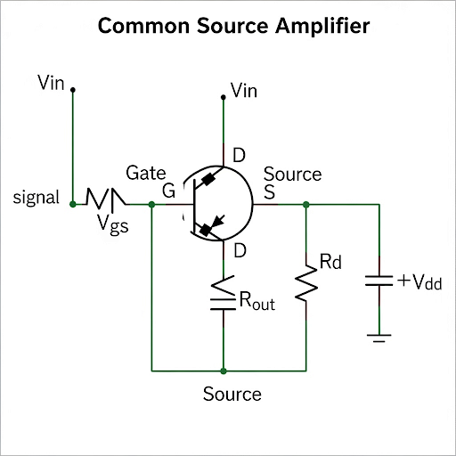
- Functionality: The common source amplifier operates by achieving voltage amplification. It primarily takes an input voltage signal at the gate terminal while sourcing the amplified output signal from the drain terminal. The source terminal remains common for both the input and output ports.
- Biasing Requirements: The operation of a CSA necessitates proper biasing, which is not based on current (as seen in BJTs) but rather a requisite gate voltage supplied to maintain the MOSFET in an active state. The gate terminal effectively needs a DC voltage higher than the threshold voltage to ensure proper functioning, and the drain voltage must also be sufficiently high to prevent the device from entering the cutoff region.
- Modeling: Understanding CSAs involves transitioning into equivalent models using small signal analysis, indicating different configurations for voltage amplification and transconductance amplification.
- Relevance and Application: A solid grasp of CSAs is essential due to their critical role in microelectronic circuit design, emphasizing their practical applications in amplifying weak signals into observable voltage or current signals.
Youtube Videos

Audio Book
Dive deep into the subject with an immersive audiobook experience.
Overview of Common Source Amplifier
Chapter 1 of 4
🔒 Unlock Audio Chapter
Sign up and enroll to access the full audio experience
Chapter Content
So, dear students so we welcome to this NPTEL course on Analog Electronic Circuits, myself Pradip Mandal from E and EC department of IIT Kharagpur. So, today the module will be discussing it is Common Source Amplifier and it is it is another basic amplifier along with the common emitter amplifier.
Detailed Explanation
The common source amplifier is a fundamental type of amplifier found in analog electronic circuits. It operates similarly to the common emitter amplifier but uses MOSFET technology rather than BJT. Understanding the common source amplifier is essential for those interested in microelectronics and design. The key takeaway from this introduction is that while both amplifiers share similarities, they also differ in their operation and applications, especially in microelectronic design.
Examples & Analogies
Think of a common source amplifier like a water tap. Just as a tap adjusts the flow of water in pipes, the common source amplifier regulates the flow of electrical signals, allowing engineers to control how much signal is passed through, whether it be large amounts of data, sound, or other information. Understanding how to manipulate this 'tap' effectively aids in various electronic applications.
Biasing Mechanism
Chapter 2 of 4
🔒 Unlock Audio Chapter
Sign up and enroll to access the full audio experience
Chapter Content
So, as I say that the biasing at least at the gate need to be voltage because the DC current here if I say that I = 0. So, the gate voltage need to be sufficiently high and while you are keeping this gate voltage connected from a signal source we assume that the gate current is 0.
Detailed Explanation
In a common source amplifier, the MOSFET's gate needs to be biased with a voltage to ensure that it operates correctly. Since no DC current flows into the gate (I=0), a sufficiently high gate voltage must be maintained to turn on the transistor. This voltage should be above the threshold voltage to allow the transistor to conduct effectively. This process of setting the voltage at the gate, which influences the amplifier's performance, is critical to achieving the desired amplification.
Examples & Analogies
Imagine a light switch in a room. The switch (the gate) needs to be in the 'on' position (sufficient gate voltage) for the light (current flow) to illuminate the room (output signal). If the switch isn’t turned on (gate voltage below threshold), no light will shine, just as no current flows without the proper gate voltage.
Voltage and Signal Dynamics
Chapter 3 of 4
🔒 Unlock Audio Chapter
Sign up and enroll to access the full audio experience
Chapter Content
So, the output signal can be either voltage or current. So, if the output signal it is voltage then the corresponding amplifier it is voltage amplifier. On the other hand, at the output in case if we are detecting the signal in the form of current, then the corresponding amplifier common source amplifier can be treated as transconductance amplifier.
Detailed Explanation
The common source amplifier can produce two types of outputs: voltage and current. When the output is a voltage signal, the amplifier functions as a voltage amplifier. Conversely, if the output is a current signal, it operates as a transconductance amplifier. This capability to switch between output types makes the common source amplifier a versatile component in various applications.
Examples & Analogies
Consider a musician playing an electric guitar. Depending on how they play, they can produce different sounds—either strumming to produce a melodic output (voltage) or plucking the strings in such a way that it resonates with current (transconductance). Just as the musician can switch between playing styles, electronics can choose how to receive signals using the common source amplifier.
Saturation Region Conditions
Chapter 4 of 4
🔒 Unlock Audio Chapter
Sign up and enroll to access the full audio experience
Chapter Content
The role of keeping this output voltage that is DC voltage sufficiently high, so that the transistor remains in saturation.
Detailed Explanation
For the common source amplifier to function correctly, it must remain within the 'saturation region,' meaning the output voltage must be sufficiently high. This ensures that the transistor is 'on' and capable of amplifying the input signal without distortion. If the output voltage drops too low, the transistor might turn off or enter a nonlinear region, leading to poor amplifier performance.
Examples & Analogies
Think of a race car that needs to maintain a certain speed (output voltage) to stay on the racetrack. If it slows down too much, it risks spinning out or stalling (leaving the saturation region). Just as a driver needs to keep up speed for optimal performance, the amplifier must maintain its DC voltage to operate efficiently.
Key Concepts
-
Common Source Amplifier: A key amplifier configuration used for voltage amplification in analog circuits.
-
Biasing: The essential process to maintain the MOSFET in the active region through appropriate gate voltage.
-
Voltage Gain: Critical for determining how much an input signal is amplified at the output.
-
Transconductance: It reflects how effectively an amplifier can convert an input voltage to an output current.
Examples & Applications
In a CSA with a MOSFET, when a 1V signal is input and the amplifier's voltage gain is 10, the output voltage will be 10V.
If a CSA is configured to detect current, the output current may be calculated using the transconductance equation with the input voltage applied.
Memory Aids
Interactive tools to help you remember key concepts
Rhymes
In CS with voltage, current flows wide, keeps on boosting what's inside.
Stories
Imagine a gardener who waters plants with just the right amount, just like a CSA needs its gate voltage to thrive, allowing signals to blossom.
Memory Tools
Biasing For Optimal Amplification = BFOA (Biasing, Function, Output, Amplification)
Acronyms
CSA
Common Source Amplifier - 'Common Source' emphasizes the shared source terminal.
Flash Cards
Glossary
- Common Source Amplifier
An amplifier configuration using MOSFET that provides voltage amplification and maintains a common source terminal for input and output.
- Biasing
The method of applying a voltage bias to ensure the amplifier functions optimally.
- Voltage Gain
The ratio of output voltage to input voltage, a key parameter in amplifier performance.
- Transconductance Amplifier
An amplifier configuration where the output is a current proportional to an input voltage.
- Threshold Voltage
The minimum gate-to-source voltage necessary to allow current to flow through a MOSFET.
Reference links
Supplementary resources to enhance your learning experience.