
Amplifier Analysis
Enroll to start learning
You’ve not yet enrolled in this course. Please enroll for free to listen to audio lessons, classroom podcasts and take practice test.
Interactive Audio Lesson
Listen to a student-teacher conversation explaining the topic in a relatable way.
Introduction to Common Source Amplifier
🔒 Unlock Audio Lesson
Sign up and enroll to listen to this audio lesson

Today we'll explore the common source amplifier, a crucial component in electronic circuits. Can anyone tell me what this amplifier does?

It amplifies voltage signals, right?
Exactly! The common source amplifier mainly functions as a voltage amplifier. Now, what do you think makes it different from the common emitter amplifier?

I think it uses MOSFETs instead of BJTs?
That's correct! While both amplifiers serve similar purposes, the common source amplifier typically uses MOSFET transistors, which is essential in microelectronics. Let's proceed to the biasing methods.
Biasing of Common Source Amplifier
🔒 Unlock Audio Lesson
Sign up and enroll to listen to this audio lesson

Now, why do you think biasing is important in amplifiers?

To ensure that the amplifier remains in the correct operating region?
Exactly! In the case of a common source amplifier, the gate must be properly biased with a DC voltage above the threshold voltage. What happens if it's not biased correctly?

The amplifier might not turn on or could operate incorrectly?
Correct! Without proper biasing, the amplifier could remain off or operate in the wrong region, leading to distortions. Let's dive into the specifics of power and output voltage.
DC Analysis and Small Signal Model
🔒 Unlock Audio Lesson
Sign up and enroll to listen to this audio lesson
Now let's discuss the DC analysis of a common source amplifier. Could someone summarize what DC analysis involves?
It shows how the amplifier works with constant DC inputs, right?
Precisely! DC analysis helps us find operating points which are crucial for small-signal analysis. How do we transition to small-signal models?
By superimposing AC signals on top of the DC signals?
Exactly! This way, we can analyze how small variations in input affect output in the linear region, which is vital for understanding amplification. Let’s summarize what we've learned so far.
We cover biasing, DC analysis, and the importance of operating points!
Well done! Understanding these fundamental concepts is key to effectively working with common source amplifiers.
Introduction & Overview
Read summaries of the section's main ideas at different levels of detail.
Quick Overview
Standard
The section provides an overview of the common source amplifier's operation, its similarities and differences compared to the common emitter amplifier, and discusses its biasing methods, analysis techniques, and practical circuit applications, crucial for analog microelectronics.
Detailed
Detailed Summary
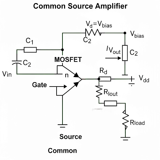
The common source amplifier (CSA) is a fundamental configuration in analog electronics used primarily with MOSFETs. This section delves into the operating principles of the CSA, outlining its similarities to the common emitter configuration found in BJTs but emphasizing critical differences.
The discussion begins with the basic operational framework of the CSA, stating that it essentially functions as a voltage amplifier where the input is a voltage signal applied at the gate, and the output can be either voltage or current. A key feature is that the source terminal is common for both input and output ports.
Next, the section addresses biasing, indicating the necessity of a voltage bias at the gate to maintain a DC operating point, particularly for enhancement mode MOSFETs. It describes how the DC voltage must remain sufficiently above the transistor's threshold to keep it in saturation, which is integral for proper amplification.
Further analysis is conducted on both DC and small-signal models that consider the transconductance of the amplifier. The DC analysis involves deriving expressions to find parameters like output voltage, where DC and AC signals can be combined. The section wraps up with a discussion on practical circuits and emphasizes the significance of understanding the square law relationship that governs MOSFET behavior, which differs significantly from BJT characteristics.
Youtube Videos

Audio Book
Dive deep into the subject with an immersive audiobook experience.
Overview of Common Source Amplifier
Chapter 1 of 5
🔒 Unlock Audio Chapter
Sign up and enroll to access the full audio experience
Chapter Content
The common source amplifier is a basic amplifier configuration alongside the common emitter amplifier. Although both share similarities, they also have distinct differences, especially in microelectronics design where MOSFETs are often utilized.
Detailed Explanation
The common source amplifier serves as a crucial component in amplification circuits, particularly when working with MOSFETs instead of BJTs (Bipolar Junction Transistors). Understanding its operation is essential for students pursuing microelectronics and VLSI design. In this context, the common source amplifier is used due to its significant role in voltage amplification and transconductance characteristics.
Examples & Analogies
Think of the common source amplifier as a water pump. Just like the pump takes in water (input voltage) and increases its pressure (output voltage), the common source amplifier takes a small input voltage and amplifies it to a larger output voltage.
Biasing of the Common Source Amplifier
Chapter 2 of 5
🔒 Unlock Audio Chapter
Sign up and enroll to access the full audio experience
Chapter Content
Biasing in the common source amplifier involves applying a voltage at the gate terminal to ensure the MOSFET operates in the saturation region. This is key to maintaining the amplifier's performance.
Detailed Explanation
The biasing process involves setting the gate voltage to a level sufficient to turn on the MOSFET. For n-channel enhancement-mode MOSFETs, the gate-source voltage (Vgs) must be higher than the threshold voltage (Vth) to keep the device in saturation. Proper biasing ensures that the transistor can amplify signals effectively without distortion.
Examples & Analogies
Imagine adjusting the brightness of a lamp by turning a dimmer switch. Similarly, biasing a MOSFET is like setting the right level of brightness—too low (like insufficient Vgs) and the lamp won't light up (the MOSFET won't amplify), while too high can cause excess heat or damage (over-driving the transistor).
DC and AC Analysis
Chapter 3 of 5
🔒 Unlock Audio Chapter
Sign up and enroll to access the full audio experience
Chapter Content
The analysis of the common source amplifier is bifurcated into DC analysis, which helps to determine the DC operating point, and AC analysis, which focuses on small-signal variations around that point.
Detailed Explanation
In more technical terms, the DC analysis helps establish the stable operating point (Q-point) of the amplifier, while the AC analysis examines how changes in input voltage (AC signals) affect the output. By analyzing both DC and small signal behaviors, one can derive important parameters such as voltage gain, input resistance, and output resistance.
Examples & Analogies
Think of DC as the foundation of a house and AC as the furniture you add. The foundation must be strong and stable (DC analysis), while the furniture can be moved around or changed (AC analysis). Just as the house stands regardless of how you arrange the furniture, the amplifier operates reliably when built on a solid DC foundation.
Output Signal Characteristics
Chapter 4 of 5
🔒 Unlock Audio Chapter
Sign up and enroll to access the full audio experience
Chapter Content
The output signal of a common source amplifier can either be in voltage or current form, leading to categorization as a voltage amplifier or transconductance amplifier based on the output type.
Detailed Explanation
The common source amplifier primarily functions as a voltage amplifier when the output is a voltage signal. However, it can also act as a transconductance amplifier when the output is a current signal. Understanding the output characteristics is essential for applications where specific signal types are required.
Examples & Analogies
Consider a faucet (common source amplifier) that can either fill a bucket (voltage output) or water a garden directly (current output). Depending on what you're trying to accomplish (bucket vs. garden), you may need to use the faucet in different ways to achieve the desired effect.
Elemental Parameters of Voltage Amplifiers
Chapter 5 of 5
🔒 Unlock Audio Chapter
Sign up and enroll to access the full audio experience
Chapter Content
When treating the common source amplifier as a voltage amplifier, it's essential to consider three key parameters: voltage gain, output resistance, and input resistance.
Detailed Explanation
These parameters are critical for defining how the amplifier will perform in a circuit. Voltage gain indicates how much the input voltage is amplified, while output and input resistance informs the circuit designer about how the amplifier interfaces with other components. The interplay of these parameters helps in optimizing circuit design.
Examples & Analogies
Think of these parameters like the specifications of a car: the voltage gain is akin to the horsepower (how much power it has), input resistance is like the fuel efficiency (how well it uses resources), and output resistance is similar to the brakes (how well it stops or regulates its output).
Key Concepts
-
Common Source Configuration: Important in analog circuits using MOSFETs.
-
Biasing: Essential for setting operating points accurately in amplifiers.
-
DC and AC Analysis: Critical to understand how amplifiers respond under various signal inputs.
Examples & Applications
Example of calculating the input and output resistance of a common source amplifier.
Illustration of the impact of proper biasing on signal amplification.
Memory Aids
Interactive tools to help you remember key concepts
Rhymes
To keep the amplifier in the zone, voltage bias is how it's grown!
Stories
Imagine a conductor named 'Voltage,' always needed to keep the 'Source' steady while the 'Drain' eagerly awaits to amplify the next signal!
Memory Tools
To remember the amplifier's workings — 'BVS' (Bias Voltage Source) keeps the Dragon (Drain) fed!
Acronyms
For MOSFET amplifiers, remember 'DC' (Drain Current) rising with 'VS' (Voltage Signal) — to keep amplifying!
Flash Cards
Glossary
- Common Source Amplifier
An amplifier configuration using a MOSFET where the source terminal is common to both input and output.
- Biasing
The method of applying a DC voltage to ensure an amplifier operates in its desired region.
- Transconductance
The ratio of the change in output current to the change in input voltage in an amplifier.
- Voltage Amplifier
An amplifier that outputs a voltage signal, using a voltage input signal.
- Operating Point
The DC conditions under which an amplifier operates.
Reference links
Supplementary resources to enhance your learning experience.