
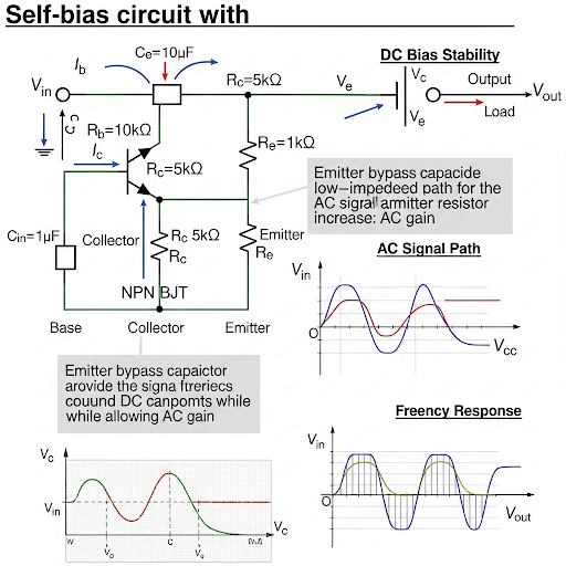
Behavior of Self-bias Circuit with Capacitors
Enroll to start learning
You’ve not yet enrolled in this course. Please enroll for free to listen to audio lessons, classroom podcasts and take practice test.
Interactive Audio Lesson
Listen to a student-teacher conversation explaining the topic in a relatable way.
Introduction to Self-biased Amplifiers
🔒 Unlock Audio Lesson
Sign up and enroll to listen to this audio lesson

Today, we're going to discuss self-biased amplifiers. Can anyone tell me what self-bias means?

Doesn't it mean that the amplifier biases itself based on its own output?
Exactly! Self-biasing helps configure the amplifier's operating point automatically. Now, what role do you think capacitors play in such circuits?

I think they help with frequency response?
That's correct! Capacitors can influence both gain and frequency response. Let’s explore how.
Gain Expression and Frequency Dependency
🔒 Unlock Audio Lesson
Sign up and enroll to listen to this audio lesson

The gain expression for a common-emitter amplifier with self-biasing is a bit complex. It includes both frequency-independent and frequency-dependent components. Who can explain what this means?

It means that some parts of the gain don't change with frequency, but others do?
Exactly! The constant part remains stable, while the part affected by frequency can change as we go through different frequencies. Can anyone recall how we find poles and zeros in this context?

Isn't it related to the capacitor's behavior at certain frequencies?
Absolutely! The zeros and poles play a crucial role in defining the circuit's frequency response.
Bode Plot and Gain Behavior
🔒 Unlock Audio Lesson
Sign up and enroll to listen to this audio lesson
Let’s now talk about plotting the Bode plot for our amplifier's gain. Who can tell me the significance of a Bode plot?
It's a way to visualize how gain changes over frequency!
Exactly! You'll see how the gain starts from low frequencies and how it changes as we hit the pole. Where do you think the key corner frequencies are located?
At the zeros and poles, right?
Correct! Those are the points to look out for when interpreting the plot. Let's summarize what we've learned about the gain in self-biased amplifiers today.
Implications of Cutoff Frequencies
🔒 Unlock Audio Lesson
Sign up and enroll to listen to this audio lesson
Now, let’s discuss cutoff frequencies. How do they dictate the performance of amplifiers in real applications?
They define the range of frequencies the amplifier can effectively work with.
Right! Specifically, we have lower and upper cutoff frequencies. The larger the bandwidth, the better the potential for audio applications. Can anyone define how we determine these cutoff frequencies?
It involves the RC time constants from our resistors and capacitors!
Great job! Understanding the right choice of capacitor is key to optimizing amplifier performance. Let’s conclude our session with a summary.
Introduction & Overview
Read summaries of the section's main ideas at different levels of detail.
Quick Overview
Standard
This section focuses on the analysis of the frequency response of a common-emitter amplifier configured with a self-biasing arrangement and a bypass capacitor. Key concepts include gain expressions, zero and pole locations, and the overall frequency response, which is influenced by the values of resistors and capacitors in the circuit.
Detailed
Detailed Summary
This section on the behavior of the self-bias circuit with capacitors in common-emitter (CE) amplifiers delves deep into understanding how capacitors affect the frequency response of an amplifier. The initial discussion revolves around the gain expression, which is reorganized to show its frequency dependency. Specifically, we find the gain expression includes both a term that is independent of frequency and a term that is frequency-dependent due to the presence of the bypass capacitor, C_E.
It is critical to recognize that due to capacitor C_E, the circuit exhibits unique features including poles and zeros that influence gain across frequencies. In particular, a zero at s = -ω (related to frequency) emerges alongside a pole at s = -ω, indicating that the circuit behavior changes significantly at these points.
A Bode plot of the gain illustrates low-frequency gain characteristics and demonstrates how the gain transitions at higher frequencies due to these poles and zeros, ultimately aligning with fixed bias configurations.
By the end of the analysis, students should grasp the interplay between capacitors and resistors in self-bias arrangements and be able to estimate cutoff frequencies that define the functional frequency limits of the amplifier's operation.
Youtube Videos

Audio Book
Dive deep into the subject with an immersive audiobook experience.
Introduction to Gain Expression
Chapter 1 of 5
🔒 Unlock Audio Chapter
Sign up and enroll to access the full audio experience
Chapter Content
Welcome back after the short break and what we are discussing so far that, the CE amplifier with the self-biased arrangement with C, that bypass capacitor C = R. And what we said is that input to output gain, it is having this expression and let us see how it looks like, maybe it is having some meaningful expression.
Detailed Explanation
This section introduces the gain expression for a common emitter (CE) amplifier with a self-bias arrangement using a bypass capacitor (C). The initial gain expression is formulated by rearranging terms to better understand the relationship between input and output signals. The use of capacitors is crucial as they affect the circuit's transient response and stability.
Examples & Analogies
Think of a CE amplifier like a water pump system where the gain is like the pressure the pump creates to push water through a pipe. The capacitors act like valves that can open or close depending on the system's needs, allowing the pump to work efficiently at different rates.
Frequency Dependence of Gain
Chapter 2 of 5
🔒 Unlock Audio Chapter
Sign up and enroll to access the full audio experience
Chapter Content
Now, this is independent of frequency; this is also independent of frequency; we can take together. So, 1 + gR you can take them together. And then if you take it as a factor. So, what we have here it is; one part is this one, which is independent of s, independent of the frequency and then we do have the other part, it is dependent on frequency.
Detailed Explanation
In this chunk, the discussion revolves around identifying parts of the gain expression that are frequency-dependent versus those that are not. The gain has components where some values remain constant regardless of frequency (like resistances) while others, linked to the capacitor, vary with frequency. Understanding this helps in designing filters and amplifiers by interpreting how signal frequencies affect amplification.
Examples & Analogies
Imagine tuning an old radio. Some frequencies (stations) come in clearly and steadily, while others might fade in and out, depending on your location. Similarly, in circuits, certain signals will always maintain their 'volume' (gain) while others may 'drop off' or change based on how quickly they pulse (frequency).
Behavior of Zero and Pole Locations
Chapter 3 of 5
🔒 Unlock Audio Chapter
Sign up and enroll to access the full audio experience
Chapter Content
In fact, if you recall that, this part is the same as the previous case when the C was not there. And due to the C, then we do have this additional part and note that it is having a zero at s = - and also a pole at s = - .
Detailed Explanation
This part discusses the implications of introducing the bypass capacitor (C) into the circuit. The presence of C creates both a zero (which can enhance gain at a specific frequency) and a pole (which can diminish gain as frequency increases). Zero and pole locations are crucial for understanding the frequency response of electronic circuits, as they specify how the output behaves at different frequencies.
Examples & Analogies
Consider a rugged mountain path as a circuit. The peaks and valleys represent poles and zeros. When climbing to a peak (zero), you're at an advantageous point where everything flows smoothly (high gain). However, as you descend into a valley (pole), the steepness can slow your progress (decrease gain). This is similar to how amplification can change with different frequencies.
Frequency Response Characteristics
Chapter 4 of 5
🔒 Unlock Audio Chapter
Sign up and enroll to access the full audio experience
Chapter Content
Now, instead of telling this is A, I should say A(s) which is function of frequency. So, let us try to sketch the bode plot of this gain; unlike the previous case, this portion is in got change.
Detailed Explanation
This section explains the transition from a theoretical gain expression to practical visualization using a Bode plot, which illustrates frequency response. The magnitude plot of the gain reveals the circuit's behavior across a range of frequencies, highlighting changes in gain due to the introduced capacitance. Understanding Bode plots allows engineers to easily identify cut-off frequencies and the overall stability of the circuit.
Examples & Analogies
Visualize a roller coaster track that rises and falls as the ride proceeds. A Bode plot is like the track map, showing the peaks (gain) at certain points where the ride (signal) feels thrilling, while the dips indicate slower sections. By plotting this, engineers can predict how enjoyable (efficient) the ride will be across different points (frequencies).
Conclusion of Gain Analysis
Chapter 5 of 5
🔒 Unlock Audio Chapter
Sign up and enroll to access the full audio experience
Chapter Content
In conclusion what we said is that, the gain here it is basically gR and the gain here it is . And location of this the pole here, which is coming from .
Detailed Explanation
The final part summarizes the outcomes of the analysis. It emphasizes the important role capacitors play in altering gain at various frequencies. The gain resonates with the product of transconductance (g) and resistance (R), with poles affecting this interaction. This conclusion ties together the earlier discussions and forms a basis for designing more efficient circuits.
Examples & Analogies
Think of baking a cake, where transconductance 'g' is like baking powder and resistance 'R' is the flour. The right mix (gain) leads to a fluffy cake (efficient amplifier). If you were to add too much baking powder (introducing too many poles), the cake might collapse (gaining less efficiently). Balancing these components is key for a solid outcome.
Key Concepts
-
Gain Expression: The mathematical representation of the output voltage gain in terms of frequency and circuit components.
-
Poles and Zeros: Specific frequencies that significantly affect the amplifier's gain, determining bandwidth and performance.
-
Frequency Response: How an amplifier’s gain varies with frequency, important for designing amplifiers for specific applications.
Examples & Applications
For a common-emitter amplifier with a capacitor, if R_E is 1k ohm and C_E is 10µF, calculate the corresponding cutoff frequencies to determine effective bandwidth.
In a self-biased amplifier, if the frequency response shows a gain of 20 dB at low frequencies and drops after reaching the pole, describe what this indicates about amplifier performance.
Memory Aids
Interactive tools to help you remember key concepts
Rhymes
In circuits where frequency flies, watch for poles, and cutoffs rise.
Stories
Imagine a singer in an amp that’s self-biased; as they sing lower or higher, the circuit adjusts, keeping volume just right, thanks to reactive parts working quietly.
Memory Tools
P.G. for Poles and Gain; remember: Poles decrease gain at specific frequency points.
Acronyms
C.A.P. for Capacitor Action in Performance
Capacitors Assist Performance by filtering and storing signals.
Flash Cards
Glossary
- SelfBias
A method in which an amplifier configures its DC operating point automatically based on its output.
- Capacitor
An electronic component that stores energy in an electric field used for filtering and coupling in amplifiers.
- Bode Plot
A graph that shows the gain and phase of a system as a function of frequency.
- Pole
A frequency at which the gain of a system drops significantly, causing a change in the amplifier's behavior.
- Zero
A frequency at which the gain of a system increases to infinity, affecting the amplifier's response.
Reference links
Supplementary resources to enhance your learning experience.