
Cascading in Common Source Amplifiers
Enroll to start learning
You’ve not yet enrolled in this course. Please enroll for free to listen to audio lessons, classroom podcasts and take practice test.
Interactive Audio Lesson
Listen to a student-teacher conversation explaining the topic in a relatable way.
Limitations of Cascading
🔒 Unlock Audio Lesson
Sign up and enroll to listen to this audio lesson

Today, we'll explore the limitations of cascading Common Emitter and Common Source amplifiers. Can anyone tell me what you think might happen when we cascade two amplifier stages?

I think the gain might increase since we have two stages?
That's one assumption, Student_1. However, it's not that simple. In reality, the gain often drops due to loading effects. Loading occurs when the input resistance of the second stage robs the first stage of some of its output. Can anyone explain how this happens?

So, it's like when you're sharing a pizza? If the second person takes a large slice, the first person ends up with less?
Exactly! That's a wonderful analogy! Each stage has its own gain, but when the output gets loaded, the overall voltage seen drops. Thus, the voltage gain might be lower than expected. Remember this: loading introduces attenuation.

What about the frequency response? Do we also see changes there?
Good question, Student_3! Yes, the overall frequency response is also affected. The lower cutoff frequency will be determined by the stage with the lowest cutoff, while the upper cutoff can change based on how the input and output capacitances interact with resistances in the cascaded setup.

So, it sounds like cascading isn't always beneficial!
You're right, Student_4. While cascading can increase gain under certain conditions, many behaviors can lead to suboptimal performance. Let's recap: the attenuating effect and varying cutoff frequencies are key limitations when cascading amplifiers.
Impact of Cutting Frequencies
🔒 Unlock Audio Lesson
Sign up and enroll to listen to this audio lesson

Now, let’s dive deeper into how cutoff frequencies play a role in cascading amplifiers. Can someone remind us what defines the cutoff frequency?
Isn’t it the frequency at which the output gain drops to a specific level?
Correct! Specifically, it's traditionally defined as the frequency where the power drops to half. Now, in cascaded configurations, can we predict what might happen to these cutoffs?
If one amp has a low cutoff, then the overall cutoff will also be low?
Exactly! The lower cutoff frequency is determined by the lowest cutoff in your stages. Conversely, the upper cutoff frequency could drop due to the interaction of resistances and capacitances between the stages, particularly Miller effects from capacitance.
Isn’t that like having a speed limit that affects multiple cars on a highway?
Great analogy, Student_3! If the slowest car sets the pace, then others can’t speed ahead. So we potentially lose frequency range in cascading setups. Does everyone follow?
Yes! We need to manage both cutoffs carefully.
To solidify, remember that the overall frequency response is dictated heavily by the weakest link in the chain, making careful consideration essential when designing amplifier stages.
The Role of Buffers
🔒 Unlock Audio Lesson
Sign up and enroll to listen to this audio lesson
Let's conclude by discussing buffers and their implications in cascading amplifiers. Who can tell me why buffers might be useful between cascaded stages?
They might help reduce loading between the stages?
Exactly! Buffers help isolate stages and allow the signal to transfer without sacrificing gain due to loading. Student_2, what should we look for in a buffer?
We want a high input resistance and low capacitance.
Right again! By ensuring the buffer has high impedance, we lessen the loading effects and use low capacitance to maintain high-frequency operation. Remember, buffers can act like a wall, preventing losses while still allowing signals to pass through.
So, should we always use buffers between stages?
Not necessarily always, but they are valuable in managing the cascading limitations we discussed. To recap, buffers can help retain both gain and frequency response when combining amplifying stages.
Introduction & Overview
Read summaries of the section's main ideas at different levels of detail.
Quick Overview
Standard
Cascading Common Emitter and Common Source amplifiers can lead to gain reduction and frequency cutoffs that are not aligned with expectations. By introducing a buffer between stages, these limitations can be mitigated, allowing for better performance in terms of gain and frequency response.
Detailed
Detailed Summary
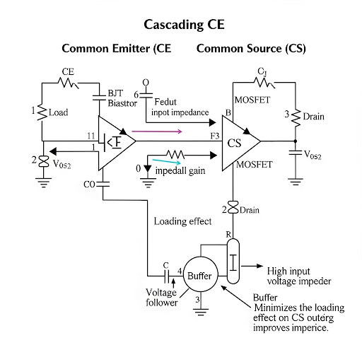
This section focuses on the limitations encountered when cascading Common Emitter (CE) and Common Source (CS) amplifiers. The discussion begins by revisiting the individual frequency responses of CE and CS amplifiers, establishing the idea that when these amplifiers are cascaded, one often hopes that the overall gain will be the product of the individual gains. However, practical scenarios reveal that both the mid-frequency gain and upper cutoff frequency are often reduced due to loading effects from the following stage.
- Cascading Limitations: Connecting the output of one amplifier stage to the input of another can introduce loading effects that attenuate the expected gain. For instance, if designated resistances from both stages are roughly equal, this could lead to significant voltage division, resulting in a notable reduction in gain.
- Effects on Frequency Response: The cascading of amplifier stages can significantly alter the expected frequency response. The lower cutoff frequency is determined by whichever stage has the lower cutoff frequency, while the upper cutoff frequency can be influenced by the input and output capacitances of the cascading amplifiers and their associated resistances—resulting in a new effective cutoff frequency that may be less than those of the individual stages.
- Buffer Implementation: To combat these limitations, the importance of implementing a buffer stage between cascading amplifiers is emphasized. Buffers can isolate the stages both in terms of DC operating points and signal transfer, effectively retaining the desired frequency response. For a buffer to be effective:
- Its input resistance should be high.
- Its output capacitance should be low to minimize loading.
In conclusion, understanding these limitations is crucial for designing effective amplification systems, and utilizing buffers is a common strategy to mitigate these cascading effects.
Youtube Videos

Audio Book
Dive deep into the subject with an immersive audiobook experience.
Introduction to Cascading and Limitations
Chapter 1 of 5
🔒 Unlock Audio Chapter
Sign up and enroll to access the full audio experience
Chapter Content
Dear students, welcome to this NPTEL online certification course on Analog Electronic Circuits, myself Pradip Mandal associated with E and EC department of IIT Kharagpur. So, today’s discussion is primarily the Limitation of Common Emitter and Common Source Amplifier particularly when it is when those blocks are getting cascaded. We have discussed about the main feature performance of common emitter and common source amplifier in our previous lectures.
Detailed Explanation
In this introduction, the instructor reiterates the focus of the current lecture, which is about the limitations encountered when cascading common emitter and common source amplifiers. Previous knowledge about these amplifier configurations is assumed, as students are expected to already be familiar with their fundamental features and performances. The purpose of today’s lecture is to dive deeper into the challenges that arise specifically in cascading setups.
Examples & Analogies
Think about stacking layers of sponge cake to make a taller cake. Each layer (or amplifier) is delicious on its own, but sometimes when you stack them up, the lower layers can become soggy and lose their texture due to the weight of the layers above. Similarly, cascading amplifiers can complicate their performance, leading to unexpected changes in gain and frequency response.
Frequency Response and Gain Expectations
Chapter 2 of 5
🔒 Unlock Audio Chapter
Sign up and enroll to access the full audio experience
Chapter Content
So, how we do that output of the first CE amplifier will be connecting to the input of the second CE amplifier. But of course, with the use of C we can isolate the DC operating point of the first stage and the second stage. … we may be expecting that the overall gain say A = A × A.
Detailed Explanation
The instructor describes how to connect two common emitter amplifiers in a cascading configuration. A coupling capacitor (C) is used to link these amplifiers while preventing DC signals from affecting their operation points. The expected overall gain from both stages is the product of their individual gains (A1 and A2). However, the reality can differ once the two amplifiers are connected due to loading effects.
Examples & Analogies
Imagine two water hoses connected in series to improve both pressure and flow. If each hose can push a certain amount of water (like each amplifier's gain), we expect the combined flow to be greater. However, if one hose is narrower (representing loading), it limits the overall flow, just like how cascading amplifiers may not deliver the expected gain due to their interactions.
Loading Effects and Gain Reduction
Chapter 3 of 5
🔒 Unlock Audio Chapter
Sign up and enroll to access the full audio experience
Chapter Content
However, once we connect the circuit and if we make the observation from the primary input to primary output we will see a significant amount of change of this gain namely this gain may drop off here to some other value and also may be the upper cutoff frequency may come down.
Detailed Explanation
When the second common emitter amplifier is connected to the first, the loading effect occurs because the output resistance of the first amplifier interacts with the input resistance of the second one. This interaction often leads to a lower actual gain and a shift in the cutoff frequency compared to expectations, meaning the output performance does not align with the theoretical calculation of A = A1 × A2.
Examples & Analogies
Consider a train that is pulling additional carriages. Initially, the train can carry a certain number of passengers (higher gain of the first amplifier). If the additional carriages are too heavy for the engine, the train might not move as fast as expected, reducing the overall capacity for passengers (gain). The loading effect is like the additional weight that reduces performance.
Upper Cutoff Frequency Considerations
Chapter 4 of 5
🔒 Unlock Audio Chapter
Sign up and enroll to access the full audio experience
Chapter Content
The second effect; second effect is on the cutoff frequency. So, let us see the cutoff frequency. So, what we can say let me clear here yeah, the cutoff frequency particularly the upper cutoff frequency it is having two candidates one is the cutoff frequency coming due to this R and then C and second one it is of course, this resistance loaded with R and then whatever the input capacitance.
Detailed Explanation
The upper cutoff frequency is important in determining the bandwidth of the cascaded amplifiers. The overall cutoff frequency will be defined by the lowest value among two candidates: one from the original setup (based on R and C) and the other influenced by loading effects when cascading occurs. This change means that the frequency response might be limited or shifted due to the loading resistances.
Examples & Analogies
Imagine you are using a microphone connected to a speaker through multiple cables. If one cable is low quality or too long, it might distort the sound and limit the range of frequencies you can hear clearly. Just as with sound, cascading amplifiers can hinder the frequency response, causing some frequencies to get lost along the way.
Mitigation with Buffer Circuits
Chapter 5 of 5
🔒 Unlock Audio Chapter
Sign up and enroll to access the full audio experience
Chapter Content
If we put a buffer; so if we put a buffer say or say some intermediate circuit having some important feature we will be discussing that such that, the input resistance of this stage; call R . If it is quite high then whatever the attenuation it will be getting introduced by R and R will be minimized.
Detailed Explanation
The use of buffer amplifiers can help address the limitations experienced in cascading configurations. A buffer can isolate the stages, ensuring that the next amplifier does not influence the previous one. High input resistance and low output capacitance in the buffer will minimize voltage loss and maintain frequency response, allowing for more effective amplification.
Examples & Analogies
Think of a buffer as a middle person in a conversation. If you have a friend who often interrupts or changes the tone of your discussion (the loading effect), having a neutral person to communicate between you helps keep the original message intact. In electronics, the buffer allows each amplifier to work more effectively without negatively impacting the other.
Key Concepts
-
Cascading Limitations: The gain may drop due to loading effects when connecting multiple amplifier stages.
-
Frequency Response: The overall frequency response can differ from individual stages due to interactions between stages.
-
Buffer Importance: Buffers help isolate amplifier stages to retain expected gain and frequency response.
Examples & Applications
When cascading two identical CE amplifiers, if their gains are expected to multiply, the actual output may show less than anticipated due to loading effects.
In a practical circuit, if the first CE amplifier has a cutoff frequency of 1 kHz and the second 2 kHz, the overall response could only reach 1 kHz due to cascading limitations.
Memory Aids
Interactive tools to help you remember key concepts
Rhymes
Cascading can cause gain to fall, load it first, and it affects all.
Stories
Imagine a relay race, where each runner depends on the performance of the previous, just like amplifier stages—if one slows down, all lag behind.
Memory Tools
To remember the buffer requirements, think 'HICE': High input resistance, Low capacitance, Effective isolation.
Acronyms
LOAD
'Loss Of Amplification due to Loading when cascading.'
Flash Cards
Glossary
- Common Emitter Amplifier (CE)
A transistor amplifier configuration providing high voltage gain, with common-emitter terminals for input and output.
- Common Source Amplifier (CS)
A field-effect transistor (FET) amplifier design offering considerable gain, with common-source terminals for input and output.
- Cascading
Connecting multiple amplifier stages in series to increase the overall gain.
- Loading Effect
A phenomenon where the output load of one stage reduces the effective gain of a preceding stage.
- Buffer
A circuit designed to isolate different stages of a system to prevent interference and maintain signal integrity.
- Frequency Response
A measure of an amplifier’s output response to varying frequencies of the input signal.
Reference links
Supplementary resources to enhance your learning experience.