
Cascading of Common Emitter Amplifiers
Enroll to start learning
You’ve not yet enrolled in this course. Please enroll for free to listen to audio lessons, classroom podcasts and take practice test.
Interactive Audio Lesson
Listen to a student-teacher conversation explaining the topic in a relatable way.
Understanding Cascading Limitations
🔒 Unlock Audio Lesson
Sign up and enroll to listen to this audio lesson

Today, we will discuss the cascading of Common Emitter amplifiers. Why do you think cascading allows us to increase gain?

Maybe because the output of one amplifier feeds into another?
Exactly! But what we expect is that the overall gain should be the product of individual gains. However, sometimes that doesn’t happen. Any guesses why?

Is it because of loading effects?
Good point! The output resistance of one stage can load down the next, causing the gain to drop. Let's refer to that as the 'loading effect.' Remember, LOADING = Loss of output gain in derived nodes.

Can you explain that a bit more, please?
Certainly! When the output of the first amplifier isn't designed to match the input of the second, we lose signal strength. The actual gain can be quite different than what we calculate. Let's keep that in mind.
Impact on Frequency Response
🔒 Unlock Audio Lesson
Sign up and enroll to listen to this audio lesson

Next, let’s talk about frequency response. What happens to the bandwidth when we cascade amplifiers?

Doesn't it get wider as we add more stages?
Not quite! As we cascade CE amplifiers, we can actually lower the upper cutoff frequency. Anyone remember why?
Because of the added capacitance and loading effect?
Exactly! The additional capacitance can create new cutoff frequencies, which can result in reduced overall bandwidth. When we say, 'Cascading can reduce the frequency response,' remember the acronym CRUSH: Cascading Reduces Upper SHift in frequencies.
That's a helpful way to remember it!
Using Buffers for Better Performance
🔒 Unlock Audio Lesson
Sign up and enroll to listen to this audio lesson
Now, let’s move on to buffers. Who can explain what a buffer does in this context?
Is it to isolate the two amplifier stages?
Exactly! Buffers help maintain the original signal without loading the preceding stage. What are the key features we need in these buffers?
They should have high input resistance and low capacitance, right?
Spot on! High input resistance minimizes loading, and low input capacitance helps maintain frequency response. You might think of 'HIGH Is LOW' as a memory aid: HIGH resistance, LOW capacitance!
That’s clever!
Analyzing Gain and Bandwidth
🔒 Unlock Audio Lesson
Sign up and enroll to listen to this audio lesson
Let’s analyze how to calculate the overall gain in cascaded amplifiers. If you have two amplifiers, what's the formula?
It's supposed to be their individual gains multiplied together, right?
Correct! But factor in that attenuation we talked about. So, the actual gain is: overall gain = Gain1 × Gain2 × Attenuation. Does everyone understand the adjustment due to the loading effect?
Yes, it's about how the output resistance affects the input of the next stage.
Perfect! Remember, ATTAIN ADAPTATION = Adjust total gain from individual techniques. Keep practicing this concept!
Introduction & Overview
Read summaries of the section's main ideas at different levels of detail.
Quick Overview
Standard
The cascading of Common Emitter and Common Source amplifiers can lead to limitations in gain and bandwidth due to loading effects and altered frequency responses. The introduction of buffer circuits is recommended to mitigate these effects and achieve meaningful amplification.
Detailed
Cascading of Common Emitter Amplifiers
In this section, we explore the limitations of Common Emitter (CE) and Common Source (CS) amplifiers when cascaded. Previously, we reviewed the performance characteristics of these amplifiers, but when connected sequentially, they exhibit unintended behaviors. The expected gain from cascading is not realized due to loading effects between stages.
Key Points Covered:
- Expected Behavior: In cascading two identical CE amplifiers, the combined gain and frequency response should ideally be a multiplication of gains and bandwidths of individual amplifiers.
- Reality Check: However, real connections often result in lower gain and possible bandwidth reduction due to the loading effect, where the output of the first amplifier influences the input of the second amplifier.
- Attenuation Factors: The gain dropped due to the loading factor, calculated based on relative input and output resistances.
- Upper Cutoff Frequency: The cascading affects the upper cutoff frequency by introducing additional capacitance that can alter frequency response.
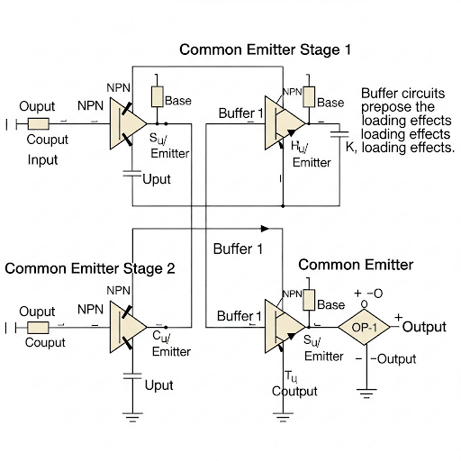
- Use of Buffers: Introduction of buffer circuits can help alleviate these cascading effects. Buffers serve to isolate stages, maintaining signal integrity and frequency response.
- Requirements for Buffers: Effective buffering requires high input resistance and minimal input capacitance to ensure the primary stages remain unaffected.
This effective understanding of cascading and buffering is vital as it informs design choices for practical analog electronic systems, ensuring optimal performance.
Youtube Videos

Audio Book
Dive deep into the subject with an immersive audiobook experience.
Understanding Cascading in Amplifiers
Chapter 1 of 4
🔒 Unlock Audio Chapter
Sign up and enroll to access the full audio experience
Chapter Content
Dear students, welcome to this NPTEL online certification course on Analog Electronic Circuits. Today’s discussion is primarily about the Limitation of Common Emitter and Common Source Amplifier particularly when these blocks are getting cascaded. We have discussed the main feature performance of common emitter and common source amplifier in our previous lectures. Let’s look into the flow and understand where we stand today.
Detailed Explanation
In this introduction, the speaker welcomes students to the course and sets the context for today's lesson. The focus is on understanding the limitations of both Common Emitter (CE) and Common Source (CS) amplifiers when they are cascaded together in a circuit. This is important because combining stages can lead to unexpected behaviors and performance issues that need to be addressed.
Examples & Analogies
Think of cascading amplifiers like building a multi-story building where each floor (amplifier) adds height (gain) to the structure. However, if the foundation (circuit design and limitations) isn't strong enough, the building might sway or even collapse (performance issues), stressing the importance of addressing limitations before stacking additional floors.
Frequency Response in Cascaded Amplifiers
Chapter 2 of 4
🔒 Unlock Audio Chapter
Sign up and enroll to access the full audio experience
Chapter Content
To appreciate the limitations or restrictions in common emitter or common source amplifier configurations, we revisit the frequency response of these amplifiers. We will see that when we cascade two common emitter amplifiers, the expected gain and bandwidth can change significantly.
Detailed Explanation
When cascaded, it’s anticipated that the overall gain would be the product of the gains from each amplifier. However, the frequency response can be affected due to loading conditions introduced by the cascading. Each stage can impact the frequency cutoffs, which are boundaries that define the operational limits of the amplifier’s frequency response.
Examples & Analogies
Imagine you have two speakers (amplifiers) connected to create a stereo sound. You expect the combined sound to be loud (gain) and clear across all frequencies. But if one speaker is too close to a wall (circuit loading), it might distort sound (frequency response), making your listening experience less enjoyable.
Cascading Impact on Gain and Frequency Cutoff
Chapter 3 of 4
🔒 Unlock Audio Chapter
Sign up and enroll to access the full audio experience
Chapter Content
Expectedly, when two amplifiers are cascaded, if the first has a gain of A1 and the second A2, overall gain should be A = A1 × A2. However, we observe that after cascading, there's a notable reduction in gain and a shift in the cut-off frequencies.
Detailed Explanation
Upon cascading, the gain observed at the output isn't simply the product of the gains from the individual stages due to loading effects. The upper and lower cutoff frequencies also shift, meaning that the bandwidth is affected. This deviation can lead to disappointing performance if not accounted for, as the cascaded system may not function as effectively as anticipated.
Examples & Analogies
Consider a relay race where each runner (amplifier) is expected to complete their segment in a set time, contributing to an overall fast race time. If one runner stumbles (loading effect), not only does it slow them down (gain), but it also makes the final performance (cutoff frequency) worse than just the sum of their parts.
Role of Buffers in Cascading
Chapter 4 of 4
🔒 Unlock Audio Chapter
Sign up and enroll to access the full audio experience
Chapter Content
To address these limitations, we introduce a buffer between the cascaded amplifiers. The buffer isolates stages, reducing loading effects and helping to retain the desired frequency response.
Detailed Explanation
A buffer acts as an intermediary that can prevent the loading effects of one amplifier on the next. By using a buffer with a high input resistance and low output capacitance, the integrity of the original signal can be maintained, thereby improving overall performance in a cascaded configuration.
Examples & Analogies
Think of a buffer like a relay runner who keeps the baton (signal) smooth and uninterrupted as it is passed between runners (amplifiers). By ensuring that each runner doesn’t overly exert influence on the next, the race can continue smoothly without any deceleration or distortion, ensuring better overall performance.
Key Concepts
-
Loading Effect: The interaction between output and input resistances causing gain loss.
-
Importance of Buffers: Buffers maintain signal strength and frequency response.
-
Cascading Gain Calculation: Overall gain is the product of individual gains adjusted for attenuation.
Examples & Applications
When two CE amplifiers each having a gain of 10 are cascaded, the expected gain is 100. If loading reduces the effective gain to 30, the actual overall gain is this attenuation factored into calculations.
In experiments with CS amplifiers, it was found that the use of a buffer increased the bandwidth significantly, from 1kHz to 5kHz, thus demonstrating the buffer's utility in maintaining performance.
Memory Aids
Interactive tools to help you remember key concepts
Rhymes
Cascading is fun, but remember the loading; a buffer helps keep the signal from corroding.
Stories
Imagine a basketball player passing the ball to another player; if the first player has a weak throw (like a loading effect), the next player won’t perform well unless a strong pass (buffer) is made.
Memory Tools
To remember the importance of buffers: 'HIGH Is LOW': High input resistance, Low capacitance.
Acronyms
C.R.U.S.H - Cascading Reduces Upper Shift in frequencies.
Flash Cards
Glossary
- Cascading
Connecting multiple amplifiers in sequence such that the output of one feeds into the input of the next.
- Loading Effect
The decrease in gain or signal strength caused by the interaction of circuit components, particularly the output of one stage affecting the input of the next.
- Buffer
A circuit that isolates one stage of amplification from another to prevent loading effects and maintain frequency response.
- Gain
The ratio of output signal to input signal, typically expressed in decibels (dB).
- Frequency Response
The range of frequencies over which an amplifier operates effectively, defined by its cutoff frequencies.
Reference links
Supplementary resources to enhance your learning experience.