
Use of Buffers in Cascading
Enroll to start learning
You’ve not yet enrolled in this course. Please enroll for free to listen to audio lessons, classroom podcasts and take practice test.
Interactive Audio Lesson
Listen to a student-teacher conversation explaining the topic in a relatable way.
Introduction to Limitations in Cascading Amplifiers
🔒 Unlock Audio Lesson
Sign up and enroll to listen to this audio lesson

Today, we are going to explore the limitations of cascading common emitter amplifiers. Can anyone tell me why we cascade amplifiers in the first place?

To increase the overall gain.
Exactly! That's a key reason. However, when we connect them, we may encounter something unexpected. What do you think might happen to the expected gain?

It might be lower than expected because of loading effects?
Correct! The gain often drops due to loading effects where the output of one stage interacts with the input of the next. Let’s remember the acronym GAIN - Gain Attenuation In Noise - it can help us recall how interconnected stages influence gain.

What about the frequency response? Will that also be affected?
Good question! Yes, the frequency response can also change. Typically, the overall cutoff frequencies will be affected by the lower cutoff frequency of the cascaded stages, reducing bandwidth.

So how can we solve these issues?
Great point! One effective solution is to use buffers. We will delve into how buffers help to maintain gain and frequency response. Remember, a buffer isolates stages and prevents attenuation.
The Role of Buffers
🔒 Unlock Audio Lesson
Sign up and enroll to listen to this audio lesson

Buffers are crucial in maintaining performance when cascading amplifiers. Can someone explain why we use buffers?
To avoid loading effects?
Exactly! Buffers have a high input resistance and low output capacitance, which helps maintain the original signal's integrity. Now, who can summarize the ideal qualities of a buffer?
They should have high input resistance and low output capacitance.
Well done! Buffers act as intermediaries that maintain the desired performance characteristics. Remember the phrase 'Buffer Up!' as a mnemonic to remind you of its purpose in a circuit.
How does this all tie back with frequency response?
Excellent connection! By minimizing loading effects, buffers not only help maintain gain, but they also preserve the bandwidth of the whole system.
Cascading Performance Evaluation
🔒 Unlock Audio Lesson
Sign up and enroll to listen to this audio lesson
When we evaluate cascaded amplifiers, what parameters do we need to keep in mind?
We should measure both gain and frequency response.
Spot on! The evaluation of cascaded stages should focus on overall gain, taking into account attenuation effects. Can anyone propose a method to determine the new upper cutoff frequency?
It would be the minimum of the individual cutoff frequencies?
Exactly! The higher one might dictate the overall response. Can anyone recall how we can buffer that frequency loss?
By using a buffer to isolate stages?
Right! Buffers ensure that we do not lose gain or bandwidth while cascading. The phrase 'Cascading Buffers Save Gain' is a good way to remember the virtues of buffers.
Practical Applications of Buffered Cascades
🔒 Unlock Audio Lesson
Sign up and enroll to listen to this audio lesson
Let's discuss real-world applications. Where might we see buffers being used in amplifier circuits?
In audio equipment to enhance sound quality?
Exactly! Buffers help keep the audio signal clear. What other areas can you think of?
Maybe in signal conditioning before data acquisition systems?
Great example! Buffers are vital in preparing signals for processing. Remember the acronym AUDIO - Amplifier Use of Isolation Devices to optimize audio circuits.
How can we choose the right type of buffer?
When selecting buffers, ensure high input resistance and low output capacitance. Let’s recall: 'Right Buffer, Right Settings!' as a guiding principle.
Introduction & Overview
Read summaries of the section's main ideas at different levels of detail.
Quick Overview
Standard
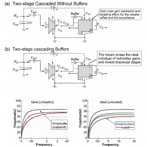
In this section, the discussion revolves around the challenges faced when cascading common emitter and common source amplifiers, particularly their impact on voltage gain and frequency response. The introduction of buffers is highlighted as a crucial remedy to mitigate these limitations, allowing for higher fidelity signal processing in cascaded amplifier designs.
Detailed
Detailed Summary of Use of Buffers in Cascading
This section investigates the limitations associated with cascading common emitter (CE) and common source (CS) amplifiers in analog electronic circuits. While cascading amplifiers usually aims to achieve higher gain and better frequency response, it is found that such configurations often lead to reduced gain and altered frequency characteristics due to loading effects and feedback from the connected stages.
Key Concepts:
- Reasons for Cascading: Amplifiers are cascaded to increase overall gain and combine the strengths of different stages. However, this can result in unexpected reductions in gain due to loading effects from output and input impedances between stages.
- Effect on Gain: The expected gain, calculated by multiplying the gains of individual stages, is often lower than anticipated due to the introduction of loading resistances. The effective gain becomes a product of individual gains modified by attenuation factors.
- Impact on Frequency Response: Cascading amplifiers typically leads to a decrease in bandwidth. While you might expect that combining two stages would result in an increased bandwidth, the effective cutoff frequencies become defined by the lower of the two stages’ cutoff frequencies, resulting in a narrower bandwidth.
- Buffer Usage: To mitigate these issues, buffers are introduced between cascaded stages. A buffer can isolate the stages by minimizing loading effects due to its high input resistance and low output capacitance, thereby maintaining the integrity of frequency response and gain.
-
Design Considerations: When designing buffer circuits, it is critical to maintain a high input resistance to limit attenuation and a small capacitance to ensure higher cutoff frequencies.
Overall, this section emphasizes the necessity of using buffers in amplifier cascading setups to maintain desirable performance, focusing on high fidelity in both gain and bandwidth.
Youtube Videos

Audio Book
Dive deep into the subject with an immersive audiobook experience.
Introduction to Buffers in Cascading
Chapter 1 of 6
🔒 Unlock Audio Chapter
Sign up and enroll to access the full audio experience
Chapter Content
And hence, we establish the need of some other circuit configurations which are referred as buffer. So, we will be discussing those things in detail. So, what are the concepts it will be covered in this today’s class.
Detailed Explanation
In this chunk, we talk about the necessity for using buffers in cascading amplifier circuits. Buffers play a crucial role in preventing issues such as signal degradation and gain loss that can arise when multiple amplifier stages are connected in series. Today’s lesson will cover the characteristics and importance of buffers, particularly in terms of maintaining signal integrity.
Examples & Analogies
Imagine trying to pour a thick smoothie through a series of funnels of different widths. If the first funnel is narrow, it slows down the flow significantly, causing a backup. However, if we place a wider funnel (the buffer) between the first narrow one and another, it allows for smoother flow, maintaining the consistency of the smoothie and avoiding clogs.
Effects of Cascading Without Buffers
Chapter 2 of 6
🔒 Unlock Audio Chapter
Sign up and enroll to access the full audio experience
Chapter Content
So, how we do that output of the first CE amplifier will be connecting to the input of the second CE amplifier. But of course, with the use of C we can isolate the DC operating point of the first stage and the second stage.
Detailed Explanation
In this chunk, we explain how to connect two common emitter amplifiers (CE amplifiers) for cascading. The capacitor (C) serves a crucial role in isolating the direct current (DC) operating points of both stages. This means that while the signal passes from the first amplifier to the second, both DC levels do not interfere with each other, which is essential for proper functioning.
Examples & Analogies
Consider a relay race where runners pass a baton. The DC level is like the runner's individual pace (operating point), and the baton passing (signal transfer) must happen smoothly without affecting each runner's speed. The baton holder (capacitor) ensures they can receive the baton without affecting their running speed.
The Impact on Gain and Frequency Response
Chapter 3 of 6
🔒 Unlock Audio Chapter
Sign up and enroll to access the full audio experience
Chapter Content
So, the overall frequency response may be having very high gain, and then the lower cutoff frequency it may be defined by whichever the lower cutoff frequency of the two stages are higher.
Detailed Explanation
Here, we discuss the anticipated gain and frequency response when cascading two common emitter amplifiers. The overall gain is expected to be the product of the gains of both stages. However, reality often differs; cascading introduces unexpected changes in both gain and the upper cutoff frequency. Lower cutoff frequencies are defined by the higher of the two stages' frequencies, but once cascaded, the circuit may not perform as expected.
Examples & Analogies
Think of a relay in a team sport where you expect each player (amplifier) to perform at their best and help lift the team's performance (gain). However, if not trained well (improper cascading), the team doesn’t perform well despite having the players (amplifiers) who can individually excel.
Cascading and Its Consequences
Chapter 4 of 6
🔒 Unlock Audio Chapter
Sign up and enroll to access the full audio experience
Chapter Content
However, if we connect the circuit and if we make the observation from the primary input to primary output we will see a significant amount of change of this gain...
Detailed Explanation
Upon connecting the cascaded circuit, it is found that the measured gain may be significantly lower than anticipated. This is due to the loading effects introduced by the interacting resistances of the cascaded amplifiers. The unexpected changes in gain and the upper cutoff frequency stem from the interaction of the internal resistances and capacitances between stages.
Examples & Analogies
Imagine setting up a series of dominoes where you expect a chain reaction. If some dominoes are placed too close, they might tip over too easily or interact in unintended ways, causing the expected chain reaction to fail. Similarly, loading effects disrupt the gain in cascading amplifiers.
Mitigating Effects with Buffers
Chapter 5 of 6
🔒 Unlock Audio Chapter
Sign up and enroll to access the full audio experience
Chapter Content
So, to avoid the loading effect at this node what you are looking for is that the input resistance of the second CS amplifier or CE amplifier...
Detailed Explanation
To counteract the loading effects that affect gain and frequency response in cascaded configurations, the use of buffers is advised. Buffers with high input resistance and low output capacitance help minimize these effects, thereby preserving the characteristics of the original signal while enabling effective cascading.
Examples & Analogies
Consider a high-rise building where elevators (buffers) are used. By making sure elevators can handle different load capacities (high input resistance) and move swiftly (low output capacitance), they ensure that moving people between floors (signal transfer) remains efficient without delays or overloads that can slow down the process.
Summary of Buffer Requirements
Chapter 6 of 6
🔒 Unlock Audio Chapter
Sign up and enroll to access the full audio experience
Chapter Content
So, in summary the requirement of the buffered it is the following...
Detailed Explanation
The chunk wraps up by summarizing the requirements for an effective buffer in cascading circuits. High input resistance minimizes signal loading, and low output capacitance prevents excessive cutoff frequency degradation. These features are critical to preserving the performance of the overall cascaded amplifier system.
Examples & Analogies
Just like a good coffee filter that allows all the flavors through while keeping the grounds (noise and interference) out intact, a well-designed buffer enhances the key signal while filtering out the unwanted overhead that might come from cascading different amplifier stages.
Key Concepts
-
Reasons for Cascading: Amplifiers are cascaded to increase overall gain and combine the strengths of different stages. However, this can result in unexpected reductions in gain due to loading effects from output and input impedances between stages.
-
Effect on Gain: The expected gain, calculated by multiplying the gains of individual stages, is often lower than anticipated due to the introduction of loading resistances. The effective gain becomes a product of individual gains modified by attenuation factors.
-
Impact on Frequency Response: Cascading amplifiers typically leads to a decrease in bandwidth. While you might expect that combining two stages would result in an increased bandwidth, the effective cutoff frequencies become defined by the lower of the two stages’ cutoff frequencies, resulting in a narrower bandwidth.
-
Buffer Usage: To mitigate these issues, buffers are introduced between cascaded stages. A buffer can isolate the stages by minimizing loading effects due to its high input resistance and low output capacitance, thereby maintaining the integrity of frequency response and gain.
-
Design Considerations: When designing buffer circuits, it is critical to maintain a high input resistance to limit attenuation and a small capacitance to ensure higher cutoff frequencies.
-
-
Overall, this section emphasizes the necessity of using buffers in amplifier cascading setups to maintain desirable performance, focusing on high fidelity in both gain and bandwidth.
Examples & Applications
An audio amplifier system that cascades multiple CE amplifiers to achieve desired sound levels ensuring that buffers are used to maintain clarity.
A data acquisition system that uses CS amplifiers, with buffers to manage signal integrity across stages.
Memory Aids
Interactive tools to help you remember key concepts
Rhymes
To gain without pain, use a buffer in chain.
Stories
A signal travels through several gates. With each gate being an amplifier, it loses clarity. A buffer appears to save the day, ensuring the signal maintains its way.
Memory Tools
Remember GAIN - Gain Attenuation In Noise - to recall the issues with cascading amplifiers.
Acronyms
AUDIO - Amplifier Use of Isolation Devices, to optimize audio circuits.
Flash Cards
Glossary
- Common Emitter Amplifier
A type of amplifier configuration characterized by high gain and moderate frequency response, typically used in signal amplification.
- Common Source Amplifier
An amplifier configuration commonly used in FET circuits, similar in function to a common emitter amplifier.
- Loading Effect
The effect on an amplifier's performance due to the interaction of output and input impedances of successive stages.
- Buffer
An electronic component that isolates stages of an amplifier, typically characterized by high input resistance and low output capacitance.
- Frequency Response
The range of frequencies over which an amplifier can operate effectively.
Reference links
Supplementary resources to enhance your learning experience.