
Historical Context and Evolution of Testability Strategies
Enroll to start learning
You’ve not yet enrolled in this course. Please enroll for free to listen to audio lessons, classroom podcasts and take practice test.
Interactive Audio Lesson
Listen to a student-teacher conversation explaining the topic in a relatable way.
Introduction to Early Testing Approaches
🔒 Unlock Audio Lesson
Sign up and enroll to listen to this audio lesson

To start off, let's explore the very early approaches to testing in electronics. Can anyone tell me how testing began in the 1940s through the 1960s?

Was it mainly manual inspections back then?
Exactly! Early test methods involved manual inspections where engineers would physically check components, often using multimeters for continuity checks. This worked well for simple analog circuits.

But wouldn't that be hard as circuits got more complex?
Yes, that's a great observation! As complexity increased, these methods became less effective, leading to the development of functional testing. Functional testing involved applying input signals and observing outputs to verify circuit behavior.

Did functional testing cover everything?
Not quite. While it checked overall functionality, it couldn't verify individual components, making it inefficient with larger systems.

So, what happened next in the evolution of testing?
Good question! Let's move on to the emergence of automated testing techniques in the 1970s.
Automated Testing and Its Impact
🔒 Unlock Audio Lesson
Sign up and enroll to listen to this audio lesson

Now, shifting to the 1970s, automated test equipment played a crucial role. Can anyone explain what this automation involved?
Was it about machines doing testing instead of people?
Yes! Automated Test Equipment, or ATE, allowed for applying test vectors automatically and measuring results accurately, thus minimizing human errors.
How did it adapt to more complex circuits?
ATE systems evolved to handle increasingly intricate testing, which included using digital oscilloscopes and pattern generators.
What about faults? How did testing adapt there?
Great point! This led to the introduction of fault models, which helped simulate possible faults in the system. For example, the 'stuck-at fault' model helped engineers understand specific failure conditions.
Were there tools to help with simulation?
Absolutely! Simulation tools started to be used, allowing engineers to model circuit behavior before physical creation, thus enhancing overall testing accuracy.
Design for Testability
🔒 Unlock Audio Lesson
Sign up and enroll to listen to this audio lesson
Let’s dive into the 1990s, where Design for Testability, or DFT, became pivotal. Who can tell me what DFT means?
It’s about making circuits easier to test right from the design stage, right?
Exactly! DFT strategies like scan chains improved testability significantly. Can anyone explain what scan chains do?
They connect sequential logic elements together, making it easier to access the internal state?
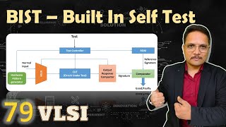
Well stated! This connection allows detection of faults more straightforwardly. Combined with Built-In Self-Test, or BIST, circuits can perform self-testing reducing reliance on external equipment.
What effect did Boundary Scan have on testing?
The IEEE 1149.1 standard allowed efficient testing of chip interconnections, especially important for densely packed systems. It enabled testing for faults like open or short circuits without manual probing.
How did that change the landscape?
It fundamentally improved accessibility in testing and paved the way for innovations in how we approach complex designs.
Modern Testability Strategies
🔒 Unlock Audio Lesson
Sign up and enroll to listen to this audio lesson
Now, let's discuss the transition into modern testing as we enter the 2010s. With SoCs becoming the norm, what are some challenges we face?
I think there are just more things to test compared to earlier designs.
That's right! Testing now requires advanced techniques for better coverage and fault detection. Can anyone explain what at-speed testing is?
It's testing the circuits at their actual operating speeds?
Exactly! This is essential for detecting timing-related faults. Coupled with advanced fault models, it allows for representing complex errors that weren't covered before.
And what about the need to minimize test data?
Good point! Test compression and minimization are crucial for managing the size of ICs and ensuring effectiveness in testing with reduced time.
What do you think the future holds for testing strategies?
The future will likely embrace revolutionary technologies like AI and quantum computing, driving further advancements in automated testing.
Introduction & Overview
Read summaries of the section's main ideas at different levels of detail.
Quick Overview
Standard
The evolution of testing strategies in electronic systems has progressed hand-in-hand with technological advancements in integrated circuits. Starting from rudimentary manual inspections, testing methods transitioned to functional approaches in the early years, leading to automated testing and Design for Testability principles in later decades, highlighting a continuous improvement in efficiency and capabilities.
Detailed
Historical Context and Evolution of Testability Strategies
The progression of testability strategies in electronic systems is fundamentally linked to the advancements in integrated circuits (ICs), microprocessors, and system-on-chip (SoC) technologies. As electronic systems evolved, verifying their functionality and reliability through testing transformed into a significant challenge due to increasing complexity.
Early Approaches to Testing (1940s – 1960s)
- Visual and Manual Inspection: Early test methods relied on physical inspections and basic continuity checks with multimeters, suitable for simple analog systems but inadequate as complexity increased.
- Functional Testing: Functional testing employed input signals to ensure circuit tasks were performed as intended. However, it had limitations in checking individual components.
The Emergence of Automated Testing (1970s – 1980s)
- Automated Test Equipment (ATE): The introduction of ATE transformed testing by allowing automatic application of test vectors and measurement of results, increasing accuracy and reducing time.
- Fault Models and Simulation: With rising complexity, fault models were introduced to better simulate errors, alongside the introduction of simulation tools for pre-fabrication testing, improving accuracy.
The Advent of Design for Testability (DFT) (1990s – 2000s)
- Scan Chains and BIST: DFT emerged with techniques like scan chains that connected logic elements and Built-In Self-Test (BIST) to allow circuits to test themselves, speeding up processes.
- Boundary Scan (IEEE 1149.1): This standard enhanced testability by enabling efficient interconnection testing on PCBs.
Evolution with Modern ICs and SoCs (2010s – Present)
- Advanced Techniques: New methodologies arose that required advanced test coverage and fault detection for complex ICs, including at-speed testing and new fault models.
- Test Compression and Minimization: Increasing circuit sizes necessitated approaches to minimize test data and duration while maximizing fault coverage.
The Future**: Future testing strategies will evolve alongside technology like quantum computing and AI-driven testing, addressing new complexities in circuit designs.
Youtube Videos

Audio Book
Dive deep into the subject with an immersive audiobook experience.
Introduction to Testability Strategies
Chapter 1 of 19
🔒 Unlock Audio Chapter
Sign up and enroll to access the full audio experience
Chapter Content
The history of testability strategies in electronic system design is closely tied to the growth and increasing complexity of integrated circuits (ICs), microprocessors, and system-on-chip (SoC) technologies. As electronic systems evolved from simple analog circuits to complex digital systems with millions of components, ensuring the correctness, functionality, and reliability of these systems through testing became a significant challenge. Early approaches to testing were simple but had limitations, especially as circuits grew in size and sophistication. This chapter examines the evolution of testability strategies, from basic functional testing to advanced Design for Testability (DFT) techniques, and explores how these strategies have improved testing efficiency and reduced time-to-market in modern electronic systems.
Detailed Explanation
This chunk introduces the topic of testability strategies and explains how they have developed alongside technological progress in electronics. Originally, testing methods were very simple, but as technology grew more complex, these methods were found to be inadequate. The section highlights the transition from basic functional testing to more sophisticated Design for Testability (DFT) techniques, marking the journey of testing evolution aimed at improving efficiency and lowering the time required to bring products to market.
Examples & Analogies
Think of testability strategies as the evolution of instruction manuals for assembling furniture. In the beginning, the manuals offered only basic diagrams, which worked well for simple pieces. However, as furniture designs became more complex, such as multi-functional items with intricate assembly, the manuals had to evolve to include detailed steps and tips for efficient assembly, ensuring that customers could successfully complete the tasks without frustration.
Early Approaches to Testing (1940s – 1960s)
Chapter 2 of 19
🔒 Unlock Audio Chapter
Sign up and enroll to access the full audio experience
Chapter Content
The initial stages of electronic circuit testing were rudimentary and heavily dependent on manual inspection and basic functional checks.
Detailed Explanation
This chunk highlights how testing practices in the early days of electronics relied mainly on manual methods. Technicians performed physical inspections of circuits and used simple continuity checks with multimeters to determine if components were functional. These methods worked for simpler analog circuits but became ineffective as the complexity of systems increased.
Examples & Analogies
Imagine a time when cars were much simpler, and all you needed to fix them was a shovel and a wrench. In those early days, car mechanics could easily spot problems just by looking under the hood. However, as cars evolved and became filled with advanced technology like computers, it became much more challenging to diagnose issues, requiring specialized tools and techniques to get the job done.
Functional Testing in Early Systems
Chapter 3 of 19
🔒 Unlock Audio Chapter
Sign up and enroll to access the full audio experience
Chapter Content
As circuits became more sophisticated, engineers began to use functional testing to verify whether a circuit performed its intended tasks. Functional testing typically involved applying input signals to the circuit and measuring its output, often done by engineers during the development and manufacturing process. However, as systems became larger, the testing process remained tedious and error-prone.
Detailed Explanation
As circuits advanced in complexity, the approach of functional testing emerged. This involved inputting specific signals into a circuit and measuring the produced output to ensure it worked as intended. While functional testing allowed engineers to assess whether the entire system functioned correctly, it still faced challenges, such as being unable to effectively test individual components within a circuit and becoming inefficient as systems grew larger.
Examples & Analogies
Consider functional testing like a teacher checking if a student graduated by only looking at their final report card. While the report card gives a glimpse of their overall performance, it doesn't reveal how the student fared in individual subjects or skills. Just as we need to assess each subject to understand a student's strengths and weaknesses, engineers need to test individual components for deeper insights into circuit performance.
Challenges with Functional Testing
Chapter 4 of 19
🔒 Unlock Audio Chapter
Sign up and enroll to access the full audio experience
Chapter Content
Functional testing could only check the overall functionality of a system, not the individual components. Additionally, the increasing complexity of circuits led to longer test times, making this process inefficient.
Detailed Explanation
This chunk explains significant limitations of functional testing. While functional tests could determine if a system as a whole was working, they could not isolate and evaluate individual components. Moreover, the growing complexity of circuits resulted in extended testing durations, complicating the process and making it less efficient as engineers struggled to identify specific issues.
Examples & Analogies
Think of a car that runs smoothly but has an engine light on, indicating something might be wrong. If you only perform a comprehensive road test (like functional testing), you might miss the specific issue causing the light to be on. Just like in car maintenance, where mechanics need to check individual parts to diagnose issues accurately, engineers need more detailed tests to pinpoint problems in a circuit.
The Emergence of Automated Testing (1970s – 1980s)
Chapter 5 of 19
🔒 Unlock Audio Chapter
Sign up and enroll to access the full audio experience
Chapter Content
As integrated circuits became more complex and more components were packed into smaller areas, manual testing became impractical. During the 1970s and 1980s, the development of automated testing marked a significant shift in the approach to testing, leading to the development of early testability strategies.
Detailed Explanation
This chunk discusses the critical evolution from manual to automated testing as integrated circuits grew in complexity during the 1970s and 1980s. With the increasing number of components, manual methods became insufficient, which spurred innovation in automated testing tools and techniques that improved the accuracy and speed of testing processes.
Examples & Analogies
Imagine trying to assemble a Lego set with thousands of small pieces. While you could do it by hand if you had a small box of blocks, it would be impractical for a vast set. Similarly, engineers found that just as Lego enthusiasts created assembly machines for large sets, they needed automated testers to keep up with the intricacy of modern electronic circuits.
Automated Test Equipment (ATE)
Chapter 6 of 19
🔒 Unlock Audio Chapter
Sign up and enroll to access the full audio experience
Chapter Content
In the 1970s, the rise of Automated Test Equipment (ATE) transformed the testing landscape. ATE systems were used to apply test vectors to circuits and automatically measure the results. This allowed for faster and more accurate testing, reducing human error and testing time.
Detailed Explanation
Automated Test Equipment (ATE) brought significant advancements to the testing process during the 1970s. These systems could automatically apply predefined tests (test vectors) to integrated circuits and measure the outcomes without manual input, leading to speedier tests with improved accuracy and fewer mistakes due to human error.
Examples & Analogies
Think of ATE like a washing machine that automatically selects the washing cycle based on the fabric type. Instead of switching cycles manually after checking the clothes, the machine does the work for you, saving time and ensuring the clothes are washed properly—just as ATE reduces testing time while ensuring accuracy.
The Need for Fault Models and Simulation
Chapter 7 of 19
🔒 Unlock Audio Chapter
Sign up and enroll to access the full audio experience
Chapter Content
With the increased complexity of systems, engineers realized that testing could not solely rely on functional tests. As a result, fault models were introduced to simulate various faults in the system (e.g., stuck-at faults, bridging faults) and check how effectively the test procedure could identify these faults.
Detailed Explanation
This chunk introduces the concept of fault models that arose in response to the complexity of testing. Engineers recognized that they could not depend on functional tests alone, leading them to develop fault models. These models helped simulate specific potential faults within the system to assess whether the testing processes could adequately identify and address these issues.
Examples & Analogies
Imagine you're preparing for a fire drill at school. Instead of just teaching kids about fire safety (similar to functional testing), you conduct a simulation with various scenarios (like fault models) to see how well they would respond in different situations. By doing so, you're better prepared for a real emergency, just as engineers are with fault models in electronic systems.
Stuck-at Fault Model
Chapter 8 of 19
🔒 Unlock Audio Chapter
Sign up and enroll to access the full audio experience
Chapter Content
The stuck-at fault model became one of the first fault models used in digital circuits to represent situations where a logic gate output is 'stuck' at either a logical high (1) or low (0) value.
Detailed Explanation
This chunk discusses the 'stuck-at' fault model, a foundational concept in digital circuits used to characterize faults. In this model, a logic gate's output is frozen at either a high or low state, simulating a common fault condition that can impede performance. This model allows engineers to create effective tests to identify and mitigate these specific faults.
Examples & Analogies
Think of the stuck-at fault like a car radio that is stuck on one station. If the radio only plays one frequency, you can't switch to different songs or channels. Similarly, a logic gate stuck at a fixed value cannot operate correctly, leading to bugs in the overall digital system.
Simulation Tools
Chapter 9 of 19
🔒 Unlock Audio Chapter
Sign up and enroll to access the full audio experience
Chapter Content
The introduction of simulation tools allowed engineers to model and simulate the behavior of circuits before fabrication, significantly reducing the number of physical prototypes needed and improving the accuracy of testing.
Detailed Explanation
This chunk explains the role and impact of simulation tools that emerged in the engineering landscape. These tools enable engineers to create virtual models of circuits, allowing them to run simulations and observe circuit behavior without the need to produce physical prototypes. This development leads to fewer prototypes being made, reducing costs and improving testing accuracy.
Examples & Analogies
Consider simulation tools like a video game that lets you play out different scenarios without physically being in a situation. For instance, you can test strategies in a football game on a console before executing them in real life. Similarly, engineers can experiment with circuits through simulation tools long before they build them.
The Advent of Design for Testability (DFT)
Chapter 10 of 19
🔒 Unlock Audio Chapter
Sign up and enroll to access the full audio experience
Chapter Content
In the 1990s, with the increasing complexity of integrated circuits and the introduction of large-scale systems-on-chip (SoCs), the limitations of traditional testing methods became apparent. The sheer size of modern circuits made it difficult to perform effective functional testing or identify faults using ATE alone. This led to the development of Design for Testability (DFT), a strategy focused on incorporating testability features directly into the design of electronic systems.
Detailed Explanation
The 1990s marked a turning point in testing methodologies with the advent of Design for Testability (DFT). As integrated circuits grew increasingly complex and large-scale systems-on-chip (SoCs) came into existence, traditional testing methods faltered. DFT aimed to resolve these issues by embedding testability features directly into the design process, allowing engineers to design circuits in a way that was inherently more testable.
Examples & Analogies
Imagine how car manufacturers design vehicles with accessibility in mind. For instance, they create engine compartments that are easy to reach for servicing. Just as a well-designed car allows mechanics to diagnose issues without much hassle, DFT ensures that electronics can be tested more efficiently right from their design phase.
Scan Chains and Built-In Self-Test (BIST)
Chapter 11 of 19
🔒 Unlock Audio Chapter
Sign up and enroll to access the full audio experience
Chapter Content
Scan chains and Built-In Self-Test (BIST) techniques emerged as key methodologies in DFT to improve testability.
Detailed Explanation
This chunk elaborates on two critical DFT techniques: scan chains and Built-In Self-Test (BIST). Scan chains interconnect sequential logic elements in a way that allows for easy access to their internal states for testing. Meanwhile, BIST enables circuits to conduct self-tests without needing external testing equipment by generating test patterns internally and evaluating the results automatically.
Examples & Analogies
Imagine a self-diagnosing system in a car that runs checks when you start the engine, much like how BIST operates. Likewise, think of scan chains as a series of connected game pieces allowing a player to see and assess the game's internal state easily—these techniques enhance the overall testability and efficiency of electronic circuits.
Boundary Scan (IEEE 1149.1)
Chapter 12 of 19
🔒 Unlock Audio Chapter
Sign up and enroll to access the full audio experience
Chapter Content
The introduction of the IEEE 1149.1 standard (Boundary Scan), also known as JTAG (Joint Test Action Group), in the late 1980s and early 1990s further enhanced the testability of ICs and systems. Boundary scan allowed for efficient testing of interconnections between chips on a PCB by providing a standardized method for accessing the boundary pins of integrated circuits.
Detailed Explanation
Boundary Scan, established by the IEEE 1149.1 standard, revolutionized testing by allowing engineers to efficiently verify the connections and functionalities of interconnections between integrated circuits on printed circuit boards (PCBs). This standardized method provides a way to access the boundary pins of ICs, facilitating the testing process without requiring physical access.
Examples & Analogies
Think of Boundary Scan as a tool for checking the wiring in a complex network of Christmas lights that are distributed throughout various rooms. Instead of having to pull the lights apart to find a faulty connection, you can use a special tester that easily checks connections at each light bulb to diagnose issues—similarly, Boundary Scan simplifies PCB testing.
Evolution of DFT with Modern ICs and SoCs (2010s – Present)
Chapter 13 of 19
🔒 Unlock Audio Chapter
Sign up and enroll to access the full audio experience
Chapter Content
As semiconductor technology advanced and integrated circuits became even more complex, DFT methodologies had to adapt to new challenges presented by system-on-chip (SoC) designs and multi-core processors.
Detailed Explanation
This chunk focuses on how DFT methodologies have had to evolve continuously in response to the rapid advancements in semiconductor technology. As circuits became more complex and transitioned to system-on-chip (SoC) designs and multi-core processors, engineers faced new challenges that necessitated further improvements and innovations in testability strategies.
Examples & Analogies
Consider how mobile phones have evolved from simple devices to multi-functional computers. As the technology has advanced, manufacturers have to keep tweaking their designs and testing processes to ensure all features work across different operating environments—this constant evolution mirrors what is happening with DFT in IC design.
Advanced Test Coverage and Fault Detection
Chapter 14 of 19
🔒 Unlock Audio Chapter
Sign up and enroll to access the full audio experience
Chapter Content
Modern ICs require increasingly advanced DFT techniques that not only improve test coverage but also enhance the detection of complex faults that may arise in multi-million gate designs.
Detailed Explanation
Modern integrated circuits demand sophisticated DFT techniques to elevate both test coverage and the detection of intricate faults, especially in large designs with millions of gates. These advanced strategies ensure a thorough assessment of the device's functionality and reliability, tackling challenges brought by increased design complexity.
Examples & Analogies
Relate this to an extensive farm with various crops. A simple review might miss specific plants in distress; however, employing advanced drones to survey the fields and identify issues quickly ensures that no problems are overlooked—similarly, advanced techniques in IC testing provide comprehensive oversight of faults.
At-Speed Testing
Chapter 15 of 19
🔒 Unlock Audio Chapter
Sign up and enroll to access the full audio experience
Chapter Content
To ensure real-world performance, testing circuits at their operational speeds (at-speed testing) became increasingly important. This allows the detection of timing-related faults, which might not have been visible at lower speeds.
Detailed Explanation
At-speed testing involves running tests at the actual operational speeds of circuits. This strategy is critical for identifying timing-related faults that could lead to performance issues under normal functioning conditions. By conducting tests at true speeds, engineers can ensure that systems will perform reliably when in use.
Examples & Analogies
Think about how a professional athlete trains and competes at full speed. Their performance during practice at a slower pace might not reveal fatigue patterns that only emerge during actual competition. Similarly, at-speed testing uncovers potential issues that would only appear during normal operation.
Advanced Fault Models
Chapter 16 of 19
🔒 Unlock Audio Chapter
Sign up and enroll to access the full audio experience
Chapter Content
New fault models like delay faults, transition faults, and bridging faults are now used to simulate more sophisticated errors that might not be covered by traditional stuck-at models.
Detailed Explanation
The development of new fault models—such as delay faults, which occur when signals take longer than expected to propagate; transition faults, which relate to incorrect signal changes; and bridging faults, where unintended connections occur—ensures a higher degree of accuracy in predicting and testing contemporary integrated circuits. These sophisticated models address complexities that older models could not encapsulate.
Examples & Analogies
Consider these fault models like various types of roadblocks on a busy street. Just as specific roadblocks can cause unique delays or diversions, different fault models help engineers identify and address unique challenges that could arise within complex IC designs.
Test Compression and Minimization
Chapter 17 of 19
🔒 Unlock Audio Chapter
Sign up and enroll to access the full audio experience
Chapter Content
As the size of integrated circuits continues to grow, minimizing test data and reducing test times while ensuring thorough fault coverage have become essential.
Detailed Explanation
As integrated circuits increase in size, the management of test data and the duration of testing processes have grown more crucial. Techniques such as test compression, which condenses test data, and test minimization, which reduces the total number of test patterns required, help streamline testing while ensuring comprehensive fault coverage.
Examples & Analogies
Imagine having a large filing cabinet filled with multiple documents. If you can summarize the essential information in a few folders, it makes searching and retrieving documents much faster and more efficient. Similarly, test compression and minimization help streamline the testing process in IC design.
The Future of Testability Strategies
Chapter 18 of 19
🔒 Unlock Audio Chapter
Sign up and enroll to access the full audio experience
Chapter Content
The future of testability strategies will continue to evolve as new technologies such as quantum computing, 3D ICs, and AI-driven testing come into play.
Detailed Explanation
Exploring forward, the landscape of testability strategies is projected to become increasingly complex due to advancements in technologies like quantum computing, which will require new testing approaches given its different nature; 3D integrated circuits, which bring about new challenges; and the integration of AI that can automate testing processes and enhance fault detection.
Examples & Analogies
Think of how ride-sharing apps evolved with GPS technology and real-time data. As new technologies emerge, they quickly adapt to maintain their usefulness and efficiency. Similarly, testing strategies will adapt to leverage advances for improved performance in the field of electronics.
Conclusion on Evolution of Testability Strategies
Chapter 19 of 19
🔒 Unlock Audio Chapter
Sign up and enroll to access the full audio experience
Chapter Content
The evolution of testability strategies has been driven by the increasing complexity of integrated circuits and the growing demand for higher performance and reliability in electronic systems. From the early days of manual testing and simple functional checks to the development of Design for Testability (DFT) techniques like scan chains, BIST, and boundary scan, significant advancements have been made in how circuits are tested. As technology continues to advance, new methodologies and tools, such as AI-driven testing and quantum computing, will continue to push the boundaries of what is possible in testability and fault detection, ensuring that electronic systems remain reliable, efficient, and scalable.
Detailed Explanation
The final chunk summarizes the key takeaways from the section, emphasizing the connection between the growing complexity of integrated circuits and the evolution of testing practices. It highlights the progression from manual testing to sophisticated DFT techniques and projects that future advancements, especially in AI and quantum computing, will reshape how testing and fault detection are approached in electronics.
Examples & Analogies
This is akin to how digital photography evolved from film cameras to modern smartphones. As technological capabilities increased, new methods of capturing and printing images developed alongside them. Just as photography continues to evolve with camera technology, testability strategies will advance in tandem with electronic design expectations.
Key Concepts
-
Testability Strategies: Methods used to ensure reliability and correctness in electronic systems.
-
Design for Testability (DFT): Incorporating test features into design for improved testing.
-
Automated Test Equipment (ATE): Tools allowing automated application of tests for efficiency.
-
Functional Testing: Checking if a circuit meets its desired function through input/output testing.
-
Built-In Self-Test (BIST): Circuits that have self-testing capabilities.
-
Boundary Scan (IEEE 1149.1): Standardizing testing techniques for interconnections.
-
At-Speed Testing: Testing circuits at their operational speeds for accurate fault detection.
Examples & Applications
A simple circuit designed in the 1950s could be tested using a multimeter for continuity, showcasing early testing methodology.
In the 1980s, an engineer might use Automated Test Equipment to quickly verify the functionality of a complex microprocessor through pre-programmed test vectors.
Memory Aids
Interactive tools to help you remember key concepts
Rhymes
In the past, we would inspect with care, / Testing was manual and rarely fair, / But now with ATE, our worries go, / Tests are automated; watch the speed grow!
Stories
Imagine a team of early engineers solving circuit problems by checking each wire individually under the hope of a light glowing. As they grew tired of waiting to see which components worked, they invented a magic machine (ATE) that would do the checks quickly and accurately. Now, every circuit could be verified in minutes rather than hours!
Memory Tools
Remember the 'SAFE' approach: Scan chains, Automated testing, Fault models, and Embedded self-test – key features of DFT!
Acronyms
Use 'DFT' to remember Design For Testability, which connects testing right into the design!
Flash Cards
Glossary
- Design for Testability (DFT)
An approach that integrates testing features directly into the design of electronic systems to improve testability.
- Automated Test Equipment (ATE)
Tools used to automate the application of test vectors and measurement of results in electronic circuit testing.
- Functional Testing
A method of testing that verifies if a circuit performs its intended function by applying input signals and observing outputs.
- Scan Chains
A technique in DFT where sequential logic elements are connected in a manner allowing easy access and testing of internal states.
- BuiltIn SelfTest (BIST)
Self-testing capabilities integrated into circuits to allow internal testing without external equipment.
- Boundary Scan (IEEE 1149.1)
A standard for testing interconnections in integrated circuits that allows access to boundary pins for efficient testing.
- AtSpeed Testing
Testing conducted at the operational speeds of circuits to detect timing-related faults.
- Test Compression
The method of reducing the amount of test data that needs to be stored or transmitted.
- Fault Model
Mathematical or logical representations of common faults in a system used for testing and simulation.
Reference links
Supplementary resources to enhance your learning experience.