
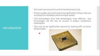
Principles of Scan Chain Implementation
Enroll to start learning
You’ve not yet enrolled in this course. Please enroll for free to listen to audio lessons, classroom podcasts and take practice test.
Interactive Audio Lesson
Listen to a student-teacher conversation explaining the topic in a relatable way.
Basic Structure of Scan Chains
🔒 Unlock Audio Lesson
Sign up and enroll to listen to this audio lesson

Today, we’ll learn about the **basic structure of scan chains**. Can anyone tell me what a scan chain is?

Isn't it just a series of flip-flops?
Exactly! A scan chain consists of flip-flops connected in series, with some key components. What’s the purpose of the *Scan-In* signal?

It's for shifting test vectors into the chain!
Correct! And what about the *Scan-Out* signal? What does it do?

It transfers the results back out for analysis.
Well done! To help remember these signals, think of SI for 'Input' and SO for 'Output'. Let’s summarize: a scan chain allows testing by connecting flip-flops with SI and SO as key signals.
Scan Chain Configuration
🔒 Unlock Audio Lesson
Sign up and enroll to listen to this audio lesson

Next, let’s explore how to configure scan chains effectively. What factors should we consider?
I think the length of the chain is important.
Absolutely! A longer chain can increase testing time. What should be balanced against the chain length?

Test coverage, right? We need to cover enough faults without taking too long.
Exactly! It’s all about finding that balance. And what about *partitioning* the scan chains?
Using multiple chains can speed up the testing process.
Correct! Partitioning can indeed enhance parallel testing. Let’s recap: when configuring scan chains, consider chain length and partitioning to optimize testing efficiency.
Incorporating Multiplexers
🔒 Unlock Audio Lesson
Sign up and enroll to listen to this audio lesson
Lastly, let’s talk about multiplexers in scan chains. What is their role?
They control whether the flip-flops work in normal mode or scan mode.
Exactly! By integrating multiplexers, designers can select the operational mode of each flip-flop. Why is this important in scan testing?
It allows access to internal states without interfering with normal operations.
Right! This flexibility is key for effective testing. Remember, MUX helps manage test access. Let’s summarize today: scan chains use multiplexers for controlled access during testing.
Introduction & Overview
Read summaries of the section's main ideas at different levels of detail.
Quick Overview
Standard
The principles of scan chain implementation involve connecting flip-flops to enable testing by creating a serial structure that allows for observation and control of internal states. Key components include Scan-In and Scan-Out signals, control signals, and considerations for chain length and partitioning.
Detailed
Principles of Scan Chain Implementation
Basic Structure of Scan Chains
A scan chain is formed by connecting flip-flops in a series, enabling straightforward observation and control of internal circuit states during testing. Major components include:
- Scan-In (SI): The point where test vectors enter the chain.
- Scan-Out (SO): The output for transferring test results out to test equipment.
- Scan Flip-Flops: Modified flip-flops that operate within the scan chain, often utilizing multiplexers for mode selection.
- Scan Enable (SE): A control signal that enables or disables scan operations, switching between normal operations and testing mode.
Scan Chain Configuration
Effective configuration is essential for optimized testability:
- Chain Length: Affected testing time; designers need to balance test coverage with the length to minimize overhead.
- Scan Chain Partitioning: In extensive systems, using multiple chains allows for concurrent testing, enhancing speed and efficiency.
Incorporating Multiplexers
Multiplexers control the operation of flip-flops by selecting between the normal operational mode and scan mode. Their integration aids in regulating test access to internal states.
Youtube Videos
Audio Book
Dive deep into the subject with an immersive audiobook experience.
Basic Structure of Scan Chains
Chapter 1 of 3
🔒 Unlock Audio Chapter
Sign up and enroll to access the full audio experience
Chapter Content
A scan chain is created by connecting flip-flops (or other sequential elements) in a series, where the output of one flip-flop is connected to the input of the next. This allows for easy observation and control of internal states during testing. The basic structure of a scan chain includes:
● Scan-In (SI): A data input that shifts test vectors into the scan chain.
● Scan-Out (SO): A data output that shifts test results from the scan chain to the external test equipment.
● Scan Flip-Flops: Flip-flops that are modified to work as part of the scan chain, often using multiplexers to switch between normal and scan operation.
● Scan Enable (SE): A control signal that enables or disables scan operation, allowing the system to switch between normal operation and scan testing mode.
Detailed Explanation
A scan chain consists of multiple flip-flops arranged in a sequence. Each flip-flop takes the output of the previous one as its input. The key components of the scan chain include:
1. Scan-In (SI) - This is the entry point where test data (called test vectors) is fed into the chain. It allows the insertion of test patterns into the circuit for testing.
2. Scan-Out (SO) - This is where the results from the circuit are sent out after testing, allowing engineers to analyze the performance and identify any faults.
3. Scan Flip-Flops - These are special flip-flops that can operate in normal mode or testing mode. In testing mode, they act like a series of registers (shift register configuration) to facilitate easy data shifting.
4. Scan Enable (SE) - This signal controls whether the scan chain operates in normal function or testing mode; when activated, the flip-flops enter scan mode, enabling testing operation.
Examples & Analogies
Imagine a relay race where each runner passes a baton to the next. Each runner represents a flip-flop; they can only pass the baton (data) to the next runner in line. The point where the first runner starts passing the baton is like the Scan-In, and the final runner handing over the baton to the coach is like the Scan-Out. During regular practices, the runners run freely (normal operation), but in testing, they all function to ensure that the baton is passed smoothly without any drops (data integrity).
Scan Chain Configuration
Chapter 2 of 3
🔒 Unlock Audio Chapter
Sign up and enroll to access the full audio experience
Chapter Content
The configuration of scan chains is a crucial step in ensuring effective testability. The following aspects must be carefully considered during scan chain implementation:
● Chain Length: The number of flip-flops in the scan chain impacts testing time. A longer chain requires more time to shift data in and out, potentially increasing test time. Designers must balance test coverage with scan chain length to minimize testing overhead.
● Scan Chain Partitioning: For large systems, multiple scan chains may be used to test different parts of the circuit simultaneously. Partitioning the scan chains effectively can help reduce scan-in/scan-out time and enhance parallelism in testing.
Detailed Explanation
Efficient scan chain configuration involves careful planning regarding the following:
1. Chain Length - The total number of flip-flops in the chain affects how quickly data can be tested. A longer chain might mean more data to shift, which in turn can increase testing time significantly. It’s essential for designers to find a balance; while longer chains may allow for more extensive fault coverage, they can also slow down testing processes.
2. Scan Chain Partitioning - In larger systems, using multiple shorter scan chains instead of one long one can be beneficial. This allows several parts of the circuit to be tested at the same time (parallel testing), which speeds up the overall testing process and reduces the time needed for data to move in and out of the chains.
Examples & Analogies
Think of a school library as the system being tested. If the library has a single long queue at the checkout desk (a long scan chain), it can take a long time for each student (data) to get checked out (tested). However, if the library has multiple smaller checkout desks (shorter scan chains), several students can check out books simultaneously, speeding up the entire process while maintaining good service.
Incorporating Multiplexers
Chapter 3 of 3
🔒 Unlock Audio Chapter
Sign up and enroll to access the full audio experience
Chapter Content
Multiplexers (MUX) are used to control whether flip-flops operate in their normal mode or are part of the scan chain. During regular operation, the flip-flops perform normal sequential logic functions, while in scan mode, they are connected in a shift register configuration. This multiplexing is essential for controlling test access to the circuit’s internal states.
● Implementation of Multiplexers: Multiplexers are integrated into the flip-flops, allowing designers to select between the circuit’s functional data path and the scan chain for test purposes.
Detailed Explanation
Multiplexers play a critical role in ensuring that flip-flops can switch between their standard functioning and testing modes. Here’s how they work:
1. Role of Multiplexers - A multiplexer can be thought of as a traffic director. It decides which pathway the data should take: either flowing through the circuit’s normal operations or entering the scan chain for testing purposes.
2. Implementation - Multiplexers are embedded within the flip-flops themselves, making it seamless for the design. During routine operations, data goes through the path defined for normal functions. However, once testing is initiated, the multiplexer reroutes the data flow through the scan chain, facilitating the testing process.
Examples & Analogies
Imagine a restaurant with a kitchen and a drive-thru service. The kitchen represents normal operation, where food is prepared and served inside. The drive-thru is the scan chain, where customers get their orders without going inside the restaurant. The employees at the order station act like multiplexers, directing customers through either the kitchen for dine-in or the drive-thru for testing. This is essential for efficient service, allowing flexibility based on customer need.
Key Concepts
-
Scan Chain: A serial arrangement of flip-flops used for testing.
-
Multiplexers: Key components controlling operation modes of flip-flops.
-
Scan Chain Configuration: Factors like chain length and partitioning affect testing efficiency.
Examples & Applications
A practical example of a scan chain involves a series of connected flip-flops that allow a technician to shift a test pattern through the register during diagnostics.
For instance, using multiple scan chains to test separate components of a circuit simultaneously can effectively reduce overall testing time.
Memory Aids
Interactive tools to help you remember key concepts
Rhymes
For testing the chains all in a line, SI brings data, SO makes it fine!
Stories
Imagine a train where every car (flip-flop) helps transport cargo (data) from one station (test point) to another, controlled by the conductors (multiplexers).
Memory Tools
Remember SC-MES: Scan Chain - Multiplexers - Enable - Structures for the layout.
Acronyms
SCAN
Shift Control Access Network
Flash Cards
Glossary
- Scan Chain
A series of flip-flops connected for testing purposes, allowing observation and control of internal states.
- ScanIn (SI)
The input point for shifting data into the scan chain.
- ScanOut (SO)
The output point for transferring results from the scan chain.
- Scan FlipFlops
Modified flip-flops that can operate in normal or scan mode.
- Scan Enable (SE)
Control signal that toggles between operational and testing modes.
- Multiplexers (MUX)
Devices that select between different input signals to control the operational mode of flip-flops.
- Chain Length
The number of flip-flops in a scan chain affecting testing time.
- Scan Chain Partitioning
Dividing scan chains into multiple segments for simultaneous testing.
Reference links
Supplementary resources to enhance your learning experience.