
Design and Analyze Combinational Logic Circuits
Interactive Audio Lesson
Listen to a student-teacher conversation explaining the topic in a relatable way.
Introduction to Combinational Logic
🔒 Unlock Audio Lesson
Sign up and enroll to listen to this audio lesson

Today, we'll start with combinational logic circuits. These are circuits where the output is solely determined by the current input values. Can anyone tell me what that means?

So, it doesn't matter what happened before? It's just about the current inputs?
Exactly! Now, why do you think this concept is important in electronics?

I guess because we can build circuits that do specific functions based solely on inputs?
That's right! Combinational circuits are essential for operations such as arithmetic calculations, data routing, and decision-making. Let’s move on to discussing logic gates.
Logic Gates
🔒 Unlock Audio Lesson
Sign up and enroll to listen to this audio lesson

Logic gates are the fundamental building blocks of combinational circuits. Can someone name a few types of logic gates?

AND, OR, NOT, NAND, NOR!
Great job! Each of these gates has a unique truth table. For example, the AND gate outputs true only when both inputs are true. Remember the acronym AND means both inputs need to be 'A' and 'B' to get 'True'.

So, can we create more complex functions using these gates?
Absolutely! We can combine these gates to create more complex circuits.
Designing a Combinational Circuit
🔒 Unlock Audio Lesson
Sign up and enroll to listen to this audio lesson
To design a combinational circuit, we follow a series of steps. What’s the first step, according to our outline?
Understand the problem, like the inputs and outputs we need.
Exactly! What comes next after that?
Create a truth table to define all possible input combinations and outputs.
Yes! And then we write the Boolean expression. What forms can we use for this?
Sum of Products (SOP) or Product of Sums (POS) forms.
Great! After simplifying the expression and implementing the circuit, we have our design.
Karnaugh Maps (K-maps)
🔒 Unlock Audio Lesson
Sign up and enroll to listen to this audio lesson
Karnaugh Maps are a tool we use to minimize Boolean expressions graphically. Who can describe how K-maps work?
They group adjacent 1's to create simplified expressions.
Correct! What sizes do K-maps come in based on the number of variables?
2-variable K-maps have 4 cells, 3-variable have 8, and 4-variable have 16.
Well done! This technique is very effective in reducing complexity in circuit design.
Common Combinational Circuits
🔒 Unlock Audio Lesson
Sign up and enroll to listen to this audio lesson
Let's explore some common combinational circuits, such as adders and multiplexers. Can anyone describe what an adder does?
An adder adds two binary numbers together!
That's right! What about multiplexers?
They select one input from multiple inputs based on a select signal.
Excellent! Understanding these common circuits will help you apply these concepts in real-world applications.
Introduction & Overview
Read summaries of the section's main ideas at different levels of detail.
Quick Overview
Standard
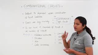
In this section, students learn about combinational logic circuits that produce output based solely on current input values. The key concepts include understanding logic gates, employing Boolean algebra, designing circuits through truth tables, and optimizing with Karnaugh maps. Additionally, common circuit types such as adders and multiplexers are discussed.
Detailed
Design and Analyze Combinational Logic Circuits
This section introduces combinational logic circuits, which are essential in digital electronics. A combinational circuit's output relies only on the current input values, meaning they possess no memory component. Key applications of these circuits include arithmetic operations (e.g., adders), data processing (e.g., encoders and decoders), routing (e.g., multiplexers), and decision-making (e.g., comparators).
Logic Gates as Building Blocks
Combinational circuits are constructed using logic gates, which include AND, OR, and NOT, among others. Each gate has specific functionalities, determined by its truth table, which illustrates the relationship between input and output values.
Boolean Algebra
To analyze and simplify combinational logic, Boolean algebra is used. It consists of various laws that help manipulate logical expressions effectively.
Designing Circuits
The design process for combinational circuits involves a series of steps:
1. Understand the Problem
2. Create the Truth Table
3. Write Boolean Expression
4. Simplify the Expression
5. Implement the Circuit
Examples and Applications
Examples of common combinational circuits discussed include the 2-to-1 multiplexer and full adders, which demonstrate practical uses. Furthermore, Karnaugh Maps are introduced as a tool for visualizing and simplifying Boolean expressions graphically.
In conclusion, a clear understanding of combinational logic circuits, their design processes, and their implementation is crucial for building advanced digital systems.
Youtube Videos


Audio Book
Dive deep into the subject with an immersive audiobook experience.
Introduction to Combinational Logic
Chapter 1 of 3
🔒 Unlock Audio Chapter
Sign up and enroll to access the full audio experience
Chapter Content
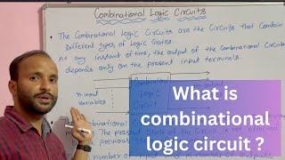
A combinational logic circuit is one where the output depends only on the current input values, not on previous input or stored values (no memory).
Combinational circuits perform:
● Arithmetic operations (adders)
● Data processing (encoders, decoders)
● Data routing (multiplexers, demultiplexers)
● Decision-making (comparators)
Detailed Explanation
A combinational logic circuit is a type of electronic circuit whose output is determined only by its present input, and it doesn't use any previous input information. This means there is no memory involved in its functioning. Combinational circuits are essential in digital systems for carrying out various tasks such as arithmetic operations, data processing, data routing, and making decisions.
Common functionalities include:
- Arithmetic operations: For example, adders are circuits that help you perform addition.
- Data processing: Devices like encoders convert data from one format to another, while decoders do the reverse.
- Data routing: Multiplexers select one input from many to send to an output, while demultiplexers take one input and send it to one of many outputs.
- Decision-making: Comparators compare two values to determine their relationship (e.g., equal, greater, less).
Examples & Analogies
Think of a combinational logic circuit as a light switch in your home. When you flip the switch (input), the light turns on or off (output) immediately based on the current switch position. It doesn't remember whether you flipped the switch before; it only reacts to the present situation.
Applications of Combinational Logic Circuits
Chapter 2 of 3
🔒 Unlock Audio Chapter
Sign up and enroll to access the full audio experience
Chapter Content
Combinational circuits perform:
● Arithmetic operations (adders)
● Data processing (encoders, decoders)
● Data routing (multiplexers, demultiplexers)
● Decision-making (comparators)
Detailed Explanation
Combinational logic circuits are fundamental components in computer systems and digital electronics, fulfilling various roles:
- Arithmetic Operations: Adders can sum binary numbers. For instance, a full adder can add two single bits and a carry-in bit, producing a sum and a carry-out bit.
- Data Processing: Encoders and decoders translate data formats, like converting multiple inputs into a binary code with an encoder or reversing it with a decoder.
- Data Routing: Multiplexers and demultiplexers manage data paths. A multiplexer selects one input from several sources, while a demultiplexer sends a single input to one of many outputs.
- Decision-Making: Comparators assess binary numbers to determine their equality or which one is greater or lesser, important in control systems and logical operations.
Examples & Analogies
Think of a restaurant menu as a data routing system. The menu (data sources) has many options (inputs), but the waiter (multiplexer) needs to select and serve your requested dish (output) based on what you order!
Types of Combinational Circuits
Chapter 3 of 3
🔒 Unlock Audio Chapter
Sign up and enroll to access the full audio experience
Chapter Content
Combinational circuits include:
- Adders: Adds binary numbers (Half/Full Adder)
- Subtractors: Subtracts binary values
- Multiplexer (MUX): Selects one input from many
- Demultiplexer (DEMUX): Sends input to one of many outputs
- Encoder: Converts multiple inputs to binary code
- Decoder: Converts binary input to multiple outputs
- Comparator: Compares binary values (equal/greater/less)
Detailed Explanation
Combinational logic circuits encompass a variety of specific functions that allow for more complex operations and data management in electronics:
- Adders: Adders can either be half adders or full adders, depending on whether they account for a carry bit or not.
- Subtractors: These circuits perform subtraction operations on binary numbers.
- Multiplexers (MUX): A multiplexer is a circuit that chooses one of several input signals and forwards the selected input into a single line.
- Demultiplexers (DEMUX): The opposite of a multiplexer, which takes a single input and channels it into one of multiple outputs.
- Encoders and Decoders: Encoders reduce multiple input lines to fewer output lines, while decoders take a binary input and produce a unique output for each possible input combination.
- Comparators: These circuits are responsible for comparing two binary values and determining their relationship.
Examples & Analogies
Imagine a shopping mall where each store represents a different type of combinational circuit. The stores (adders, subtractors, etc.) offer different services (operations) based on what you need. Just like you can either buy food or clothes in different stores, a multiplexer can either select data A or B, leading to a variety of outputs.
Key Concepts
-
Combinational Logic: Output based on current inputs without memory.
-
Logic Gates: Fundamental electronic components that perform logical operations.
-
Boolean Algebra: Mathematical framework for manipulating logic expressions.
-
Truth Table: Tabular representation of all input-output possibilities.
-
Karnaugh Maps: Visual method for simplifying Boolean expressions.
Examples & Applications
Examples of common combinational circuits discussed include the 2-to-1 multiplexer and full adders, which demonstrate practical uses. Furthermore, Karnaugh Maps are introduced as a tool for visualizing and simplifying Boolean expressions graphically.
In conclusion, a clear understanding of combinational logic circuits, their design processes, and their implementation is crucial for building advanced digital systems.
Memory Aids
Interactive tools to help you remember key concepts
Rhymes
In a circuit that’s combinational, always check the current sensation.
Stories
Imagine a farmer (AND gate) who only harvests when rain (1) and sun (1) are present - he gets no crops (0) when it's either missing.
Memory Tools
Remember the steps with 'T.C.B.S.I.' - Truth Table, Create Boolean, Simplify, Implement.
Acronyms
K-map
Keep it Make Accurate and Precise.
Flash Cards
Glossary
- Combinational Logic Circuit
A type of digital circuit whose output depends solely on the current input values.
- Logic Gates
Electronic devices that perform a basic logical function that is fundamental to digital circuits.
- Boolean Algebra
A branch of algebra that deals with true or false values and is used to simplify logic expressions.
- Truth Table
A table that shows all possible input combinations and their corresponding outputs in a combinational circuit.
- Karnaugh Map (Kmap)
A graphical method used to simplify Boolean expressions and minimize logic circuit designs.
- Multiplexer
A combinational circuit that selects one of several input signals and forwards the selected input into a single line.
- Adder
A combinational circuit that performs addition of binary numbers.
Reference links
Supplementary resources to enhance your learning experience.