
Steps to Design a Combinational Logic Circuit
Interactive Audio Lesson
Listen to a student-teacher conversation explaining the topic in a relatable way.
Understanding the Problem
🔒 Unlock Audio Lesson
Sign up and enroll to listen to this audio lesson

The first step in designing a combinational logic circuit is to understand the problem. Who can tell me what this involves?

I think it means knowing how many inputs and outputs we need.
Exactly! You need to define how many inputs you'll have and what outputs are expected. This sets the foundation for everything else. Can anyone think of examples of inputs or outputs in a circuit design?

In an adder, the inputs are the two numbers to add, and the output is the sum.
Great example! Remember, clear input and output definitions guide the design process. Let's move to the next step.
Creating a Truth Table
🔒 Unlock Audio Lesson
Sign up and enroll to listen to this audio lesson

Now that we understand our inputs and outputs, what should we do next?

Create a truth table, right?
Correct! A truth table lists all input combinations along with the expected output for each combination. Why is this table so important?

It helps us see how each input affects the output!
You're spot on! It provides a clear visual representation of the logic function we want to implement. Let’s do a quick exercise: How would a truth table look for a 2-input AND gate?
Writing Boolean Expressions
🔒 Unlock Audio Lesson
Sign up and enroll to listen to this audio lesson
Next, we write the Boolean expression from our truth table. Can anyone tell me how we do this?
We could write it in SOP form?
Exactly! In SOP, we sum the products of states for which the output is '1'. For example, if our truth table shows an output of '1' for specific input combinations, we write a term for those inputs. Can you give me a sample?
If we had inputs A and B where output Y is 1 when both are true, it would just be A·B.
Correct! So now with the expression in hand, what's our next focus?
Simplifying the Expression
🔒 Unlock Audio Lesson
Sign up and enroll to listen to this audio lesson
Now we move to simplifying our Boolean expression. Who remembers why simplification is important?
It makes the circuit design easier and more efficient, right?
Absolutely correct! Simplified expressions require fewer gates, leading to cost and space savings. We can apply Boolean laws or use K-maps. What is one advantage of using K-maps specifically?
K-maps provide a visual way to group terms for simplification!
Exactly—it helps us organize terms visually! Remember that approach when tackling complex expressions moving forward.
Implementing the Circuit
🔒 Unlock Audio Lesson
Sign up and enroll to listen to this audio lesson
Finally, we implement the circuit. What tools or components could we use for this?
We can use logic gates or even programmable devices like FPGAs!
Well done! Understanding how to implement our design ensures that it functions as intended. Remember the whole design process starts from understanding the problem to implementation. Can anyone recap the steps we discussed?
Sure! First, understand the problem, then create a truth table, write the Boolean expression, simplify it, and finally implement the circuit.
Perfect summary! These steps are critical for designing effective combinational logic circuits.
Introduction & Overview
Read summaries of the section's main ideas at different levels of detail.
Quick Overview
Standard
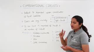
Designing a combinational logic circuit involves understanding the problem, creating a truth table, writing a Boolean expression, simplifying the expression, and finally implementing the circuit using logic gates or programmable devices.
Detailed
Steps to Design a Combinational Logic Circuit
In designing a combinational logic circuit, the process begins with a clear understanding of the problem at hand, specifically identifying the required inputs and outputs. The next step is to create a truth table that outlines all possible input combinations along with the corresponding expected outputs. After establishing the truth table, the designer will write the Boolean expression using either the Sum of Products (SOP) or Product of Sums (POS) method. Following this, the designer simplifies the Boolean expression utilizing Boolean algebra laws or Karnaugh Maps (K-maps) for efficient representation. The final step is the physical implementation of the circuit, which can be achieved with logic gates or programmable devices such as FPGAs. Understanding these steps is crucial for effectively designing functioning combinational logic circuits.
Youtube Videos


Audio Book
Dive deep into the subject with an immersive audiobook experience.
Understand the Problem
Chapter 1 of 5
🔒 Unlock Audio Chapter
Sign up and enroll to access the full audio experience
Chapter Content
- Understand the Problem
- Identify number of inputs and required outputs.
Detailed Explanation
The first step in designing a combinational logic circuit is to fully understand the problem you're solving. This includes determining how many inputs will be part of the circuit and what outputs you need. For example, if you're designing an adder, you'll need to define how many binary values (inputs) you want to add together and what the results (outputs) will look like.
Examples & Analogies
Think of it like planning a recipe. Before you start cooking, you first need to know what ingredients you need (inputs) and what dish you want to create (output). For instance, if you're making a cake, you would need to know how many eggs, cups of flour, and what the final cake should look like.
Create the Truth Table
Chapter 2 of 5
🔒 Unlock Audio Chapter
Sign up and enroll to access the full audio experience
Chapter Content
- Create the Truth Table
- Define all input combinations and expected outputs.
Detailed Explanation
The second step involves creating a truth table, which is a systematic way to organize all possible inputs and the corresponding outputs of the circuit. Each row of the truth table represents a specific combination of input values, and the corresponding output value is recorded. This helps you visualize how the circuit will behave under different conditions.
Examples & Analogies
Similar to creating a schedule for different activities throughout the day. You outline what you will do at various times (inputs), and what the outcome will be (output). If you plan to study, go for a run, or meet friends, your schedule organizes these into a clear format.
Write Boolean Expression
Chapter 3 of 5
🔒 Unlock Audio Chapter
Sign up and enroll to access the full audio experience
Chapter Content
- Write Boolean Expression
- Use SOP (Sum of Products) or POS (Product of Sums) form.
Detailed Explanation
Once you have the truth table, the next step is to translate the outputs into a Boolean expression. This can be done using two main forms: SOP (Sum of Products) which combines product terms with addition, or POS (Product of Sums) which combines sum terms with multiplication. These expressions mathematically describe how the outputs depend on the inputs.
Examples & Analogies
It’s like writing down a set of rules for a game. You summarize how points are awarded based on different actions in the game (inputs) and what the final score will be (output). For instance, 'You get a point if you score a basket AND the timer is under 10 seconds.'
Simplify the Expression
Chapter 4 of 5
🔒 Unlock Audio Chapter
Sign up and enroll to access the full audio experience
Chapter Content
- Simplify the Expression
- Apply Boolean laws or use Karnaugh Maps (K-maps).
Detailed Explanation
After writing the Boolean expression, the next step is to simplify it as much as possible. This can be achieved using Boolean laws, which help reduce complex expressions, or through Karnaugh Maps (K-maps), a visual method for minimizing expressions systematically. The goal is to have a simpler expression that requires fewer logic gates to implement.
Examples & Analogies
Consider organizing a messy room. Initially, there may be a lot of clutter (complex expression), but by identifying duplicates or items that can be discarded, you can simplify the space (simplified expression), making it easier to find what you need.
Implement the Circuit
Chapter 5 of 5
🔒 Unlock Audio Chapter
Sign up and enroll to access the full audio experience
Chapter Content
- Implement the Circuit
- Use logic gates or programmable devices (e.g., FPGA).
Detailed Explanation
The final step in designing a combinational logic circuit is to implement it physically or digitally. This can be done using various logic gates (AND, OR, NOT, etc.) or with programmable devices like FPGAs (Field Programmable Gate Arrays). The implementation step is where your design work turns into a functional circuit that can perform the intended operations.
Examples & Analogies
Imagine you've written a great script for a play. The final step is to produce the play, where actors (logic gates) perform the script in front of an audience. Just like ensuring each actor knows their role well will make the play successful, you need to make sure all components of your circuit work correctly together.
Key Concepts
-
Understand the Problem: Identify inputs and outputs.
-
Create the Truth Table: Define input combinations and outputs.
-
Write Boolean Expression: Use SOP or POS forms for representation.
-
Simplify the Expression: Apply Boolean algebra or K-maps for minimization.
-
Implement the Circuit: Use logic gates or programmable devices.
Examples & Applications
A 2-input AND gate has inputs A, B, and its output Y is a function of A and B: Y = A·B.
In a multiplexer design, you might create a truth table to determine the output based on select lines.
Memory Aids
Interactive tools to help you remember key concepts
Rhymes
In circuit design, start by knowing, inputs and outputs help keep it flowing.
Stories
Imagine designing a new game. First, you must understand what players want (inputs) and how it scores (outputs). With that knowledge, the rest follows like creating rules and buttons.
Memory Tools
U-T-B-S-I: Understand the problem, Truth Table, Boolean expression, Simplify, Implement.
Acronyms
P-T-B-S-I
Define Problem
Truth Table
Boolean Expression
Simplify expression
Implement the Circuit.
Flash Cards
Glossary
- Combinational logic circuit
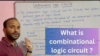
A circuit where the output depends only on the current input values.
- Truth Table
A table showing all possible combinations of input values and their corresponding outputs.
- Boolean expression
An algebraic expression made up of Boolean variables connected by logical operators.
- SOP (Sum of Products)
A form for writing Boolean expressions that sum the products of variables.
- POS (Product of Sums)
A form for writing Boolean expressions that multiply the sums of variables.
- Karnaugh Map (Kmap)
A visual tool used to simplify Boolean expressions graphically.
Reference links
Supplementary resources to enhance your learning experience.