
How I2C Works
Interactive Audio Lesson
Listen to a student-teacher conversation explaining the topic in a relatable way.
Basics of I2C Communication
🔒 Unlock Audio Lesson
Sign up and enroll to listen to this audio lesson

Today, we are going to explore how I2C communication works. Let's start with the basic structure—what are the two primary wires used in I2C?

Is it SCL and SDA?
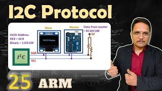
Absolutely! SCL stands for Serial Clock Line, which carries the clock signal, and SDA stands for Serial Data Line, which is used for data transmission. Together, these wires form the backbone of the I2C communication protocol. Can anyone tell me what a 'master' and 'slave' device is?

The master is the device that controls the communication, right?
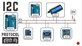
That's correct! The master generates the clock signals and initiates communication. Meanwhile, slave devices wait for their turn to send or receive data. Each slave has a unique address. Can you think of examples where this architecture would be useful?

Maybe in sensor networks where multiple sensors provide data to a single microcontroller?
Exactly! Now, let’s move on to how the data transfer happens in I2C.
Data Transfer in I2C
🔒 Unlock Audio Lesson
Sign up and enroll to listen to this audio lesson

Data in I2C is transferred in 8-bit chunks. What happens after each byte is sent?

The receiver acknowledges each byte.
Correct! Acknowledgment is crucial in confirming receipt. Now, could someone explain what start and stop conditions are?
Start condition happens when SDA goes from high to low while SCL is high, and stop condition is the opposite.
Excellent summary! Remembering these conditions is important as they signal the beginning and end of communication. Let's dive deeper into the implications of these conditions.
Practical Example using I2C
🔒 Unlock Audio Lesson
Sign up and enroll to listen to this audio lesson
Let’s look at a practical example. We have a sample code for interfacing with a temperature sensor using I2C. Can anyone recall the first step in this code?
Initializing the I2C using Wire.begin()!
Exactly! After initializing, we request data from the sensor. This is done using specific I2C commands. Why do you think we request two bytes of data?
Because the temperature sensor sends temperature data in two parts: high byte and low byte.
Right on point! The raw temperature data is combined to give us the actual temperature reading. Who can summarize how we convert this raw data?
We shift the high byte and combine it with the low byte before dividing by 128 to get the final temperature.
Great job! This hands-on interaction with I2C and real sensors helps solidify the concepts.
Introduction & Overview
Read summaries of the section's main ideas at different levels of detail.
Quick Overview
Standard
I2C, or Inter-Integrated Circuit, is a synchronous communication protocol that allows multiple devices to communicate with a microcontroller. It employs a master-slave architecture utilizing two wires for communication—SCL for the clock and SDA for data transmission. The process begins with the master generating a clock signal and ends with data transmission in 8-bit chunks, acknowledged by the receiver.
Detailed
How I2C Works
I2C (Inter-Integrated Circuit) is a widely used protocol in embedded systems for low-speed peripherals. It operates over two wires: SCL (Serial Clock Line) for the clock signal and SDA (Serial Data Line) for data transmission. This section explains the inner workings of I2C, detailing how data is transferred, how devices are addressed, and the conditions that initiate and terminate communication.
Core Concepts:
- Master Device: Initiates communication and generates the clock signal.
- Slave Devices: Each is assigned a unique 7-bit or 10-bit address to be identified by the master.
- Data Transfer: Occurs in 8-bit chunks, where the receiver must acknowledge each byte.
- Start and Stop Conditions: A communication session starts when the SDA line transitions from high to low while SCL is high (start condition), and ends when the SDA line transitions from low to high while SCL is high (stop condition).
This protocol is beneficial for connecting multiple devices (like sensors) using minimal wiring, enhancing efficiency in embedded system designs.
Youtube Videos
Audio Book
Dive deep into the subject with an immersive audiobook experience.
Master Device Initiates Communication
Chapter 1 of 4
🔒 Unlock Audio Chapter
Sign up and enroll to access the full audio experience
Chapter Content
● The master device generates the clock signal (SCL) and initiates communication.
Detailed Explanation
In the I2C communication process, there is one main device called the master. This master device is responsible for generating the clock signal, which is essential for synchronizing how data is sent and received on the bus. The master also starts the communication process by sending signals to the slave devices, letting them know that the communication is about to begin.
Examples & Analogies
Imagine a teacher (the master device) starting a class (communication) by ringing a bell (clock signal). When the bell rings, students (slave devices) know it's time to listen and respond to questions.
Unique Identification of Slave Devices
Chapter 2 of 4
🔒 Unlock Audio Chapter
Sign up and enroll to access the full audio experience
Chapter Content
● Each slave device is identified by a unique 7-bit or 10-bit address.
Detailed Explanation
In I2C, every device connected to the bus, which we refer to as a slave device, has a unique address. This address can either be 7 bits or 10 bits long, allowing each device to be identified individually. When the master sends a command, it includes the address of the specific slave device it wants to communicate with, ensuring that the correct device responds.
Examples & Analogies
Think of it like a mailing system where each house (slave device) has a unique address. When a letter (command) is sent from the post office (master), it includes the specific address, so it reaches the intended recipient.
Data Transmission Process
Chapter 3 of 4
🔒 Unlock Audio Chapter
Sign up and enroll to access the full audio experience
Chapter Content
● Data Transfer: Data is transmitted in 8-bit chunks (one byte at a time) with each byte being acknowledged by the receiver.
Detailed Explanation
Data transfer in I2C occurs in small packets called bytes. Each byte consists of 8 bits, and when the master sends a byte of data to a slave device, the slave must send back an acknowledgment (ACK) signal to inform the master that it has received the data correctly. If the slave fails to acknowledge, the master may resend the data, ensuring integrity in communication.
Examples & Analogies
Imagine a teacher passing out papers (bytes of data) to students (slave devices) one at a time. After receiving each paper, a student raises their hand (acknowledgment) to show they have received it. If no hand is raised, the teacher will try handing out the paper again.
Start and Stop Conditions
Chapter 4 of 4
🔒 Unlock Audio Chapter
Sign up and enroll to access the full audio experience
Chapter Content
● Start and Stop Conditions: Communication begins with a start condition (when the SDA line transitions from high to low while the SCL is high) and ends with a stop condition (when the SDA line transitions from low to high while the SCL is high).
Detailed Explanation
I2C communication starts with a specific action called a 'start condition.' This occurs when the data line (SDA) changes from a high state to a low state while the clock line (SCL) is still high. It indicates that a communication session is starting. Conversely, the session ends with a 'stop condition,' where the SDA line transitions from low to high while the SCL remains high. This defined sequence ensures that all devices on the bus know when to start and stop listening for communication.
Examples & Analogies
Think of a conversation that starts when someone raises their hand (start condition) to speak and ends when they lower it (stop condition). Everyone in the room understands when it’s their turn to listen or to talk.
Key Concepts
-
Master-Slave Architecture: The arrangement where one master device controls multiple slave devices.
-
Data Transfer: I2C transfers data in 8-bit chunks, with each chunk being acknowledged by the receiver.
-
Start/Stop Conditions: The signals that define the beginning and end of I2C communication.
Examples & Applications
Using I2C to interface with a temperature sensor like LM75 to read temperature values.
Interfacing various sensors (humidity, pressure) with a microcontroller using the I2C protocol.
Memory Aids
Interactive tools to help you remember key concepts
Rhymes
In I2C, two wires are key, SCL and SDA, just wait and see!
Stories
Imagine a teacher (the master) leading a class (slaves). With a bell (SCL), the teacher calls on students one by one (data transfer). Each student (slave) raises a hand to confirm they heard (acknowledgment) when called.
Memory Tools
Use 'SDA for Data Acknowledge' to remember that SDA does the data work in I2C.
Acronyms
SDA
Send Data Acknowledge - the key role of the SDA line.
Flash Cards
Glossary
- I2C
A synchronous, multi-master, multi-slave communication protocol used for connecting low-speed peripherals to a microcontroller.
- SCL
Serial Clock Line used in I2C for transmitting the clock signal.
- SDA
Serial Data Line used in I2C for transmitting data.
- Master Device
The primary device that initiates communication and provides the clock signal.
- Slave Device
Peripheral devices that communicate with the master device, identified by unique addresses.
- Start Condition
Defines the beginning of a communication session in I2C.
- Stop Condition
Defines the end of a communication session in I2C.
- Acknowledgment
A signal sent from the receiver indicating successful receipt of a byte of data.
Reference links
Supplementary resources to enhance your learning experience.