
Lab Exercise 1: Design and Analysis of a Diode Mixer
Interactive Audio Lesson
Listen to a student-teacher conversation explaining the topic in a relatable way.
Lab Objective and Materials
🔒 Unlock Audio Lesson
Sign up and enroll to listen to this audio lesson

Today, we're diving into a lab exercise on designing a diode mixer. Can anyone tell me what the main objective of this exercise is?

To design and test a diode mixer!
Exactly! We aim to understand its performance in frequency conversion. Now, what materials do we need for this exercise?

We'll need a diode, signal generator, oscilloscope, and some resistors and capacitors.
Great recall! The diode is essential as it functions in the non-linear region. Remember, we’ll work with components like the 1N4148 diode. What do you think will happen when we apply the RF and LO signals?

We’ll see how the output contains the sum and difference frequencies!
Correct! It’s all about observing those frequencies after the mixing. Let's move on to the procedure.
Procedure Steps
🔒 Unlock Audio Lesson
Sign up and enroll to listen to this audio lesson

The first step is constructing the diode mixer circuit. Why do you think circuit construction is vital?

Because if we don’t build it correctly, we won't get accurate results!
Absolutely! After constructing the circuit, we’ll apply the RF and LO signals. Can anyone explain what we need to observe when we measure the output signal?
We should look for the sum and difference frequencies on the oscilloscope.
Exactly! Understanding how to identify these frequencies is crucial for analyzing our mixer. Who can recall what frequencies are generated when we mix two signals?
The sum and difference frequencies of the input signals!
Well done! This is key to our lab exercise. Let's proceed with these steps!
Expected Outcomes and Analysis
🔒 Unlock Audio Lesson
Sign up and enroll to listen to this audio lesson
Once we've completed the procedure, what outcomes do you expect to analyze?
We should analyze the frequency components in our output!
Right! We will specifically look for both the sum frequency and the difference frequency. What do you think could affect our results?
Any errors in the circuit construction or the components we used.
Exactly! Which is why proper construction and measurement techniques are vital. Also, don’t forget to compare your results with theoretical expectations. Any predictions for how your results will compare?
I think they might be close, but there could be slight differences due to conversion loss.
That’s a very insightful prediction! Let's prepare for our hands-on lab!
Introduction & Overview
Read summaries of the section's main ideas at different levels of detail.
Quick Overview
Standard
In this section, students will engage in a practical lab exercise aimed at designing and testing a basic diode mixer. The exercise includes constructing the circuit, applying RF and LO signals, and observing the mixer’s output to understand its performance in frequency conversion.
Detailed
Lab Exercise 1: Design and Analysis of a Diode Mixer
Objective
The objective of this lab exercise is to design and test a basic diode mixer, allowing students to understand its operation in frequency conversion processes within RF systems.
Materials
- Diode (e.g., 1N4148)
- Signal Generator (RF and LO signals)
- Oscilloscope and Spectrum Analyzer
- Passive Components (resistors, capacitors)
Procedure
- Construct the Diode Mixer Circuit: Using a single diode or a diode bridge, students will set up the circuit as per the specifications.
- Apply RF and LO Signals: Once the circuit is built, students will apply RF and LO signals to the mixer.
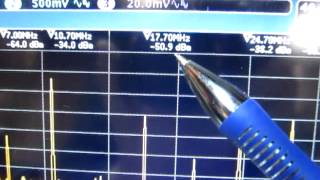
- Measure the Output Signal: Students will use the oscilloscope or spectrum analyzer to observe and measure the output signal, focusing on identifying the generated sum and difference frequencies.
This practical experience builds a deeper understanding of diode mixers and their role in RF systems, forging crucial skills for future electronic design and analysis.
Youtube Videos
Audio Book
Dive deep into the subject with an immersive audiobook experience.
Objective of the Lab Exercise
Chapter 1 of 3
🔒 Unlock Audio Chapter
Sign up and enroll to access the full audio experience
Chapter Content
Objective:
Design and test a basic diode mixer to understand its performance in frequency conversion.
Detailed Explanation
The objective is to design a simple circuit called a diode mixer, which will allow students to learn how mixing works in RF systems. By testing this mixer, students will see how effectively it converts different signal frequencies. Understanding this will help grasp fundamental concepts of frequency translation used in modern communication systems.
Examples & Analogies
Think of the diode mixer as a chef mixing two ingredients to create a new dish. Just like mixing various spices can change the flavor of food, mixing different signal frequencies can yield a new frequency that can be simpler to manage or transmit.
Materials Required
Chapter 2 of 3
🔒 Unlock Audio Chapter
Sign up and enroll to access the full audio experience
Chapter Content
Materials:
- Diode (e.g., 1N4148)
- Signal generator (RF and LO signals)
- Oscilloscope and spectrum analyzer
- Passive components (resistors, capacitors)
Detailed Explanation
To perform the experiment, specific materials are needed. The diode acts as the main component responsible for mixing the signals. The signal generator will provide the RF and LO signals needed for the process, while the oscilloscope and spectrum analyzer will help visualize the output from the mixer. Passive components like resistors and capacitors will help create a complete circuit.
Examples & Analogies
Imagine preparing a recipe; you need the right ingredients (like the diode and signal generator) and tools (like the oscilloscope and spectrum analyzer) to successfully mix flavors and assess the final dish.
Procedure for Building the Mixer
Chapter 3 of 3
🔒 Unlock Audio Chapter
Sign up and enroll to access the full audio experience
Chapter Content
Procedure:
- Construct the diode mixer circuit using a single diode or a diode bridge.
- Apply RF and LO signals to the mixer and measure the output signal.
- Observe the sum and difference frequencies using the oscilloscope or spectrum analyzer.
Detailed Explanation
The procedure involves several key steps. First, the circuit needs to be set up by connecting the components according to the provided design. Next, the RF and LO signals must be fed into the mixer. Finally, students will measure the resulting output, which could contain new frequencies produced by the mixing process. Observing these frequencies helps visualize how mixing functions in practice.
Examples & Analogies
This process is like making a smoothie; you first gather all ingredients (build the circuit), then blend them together (apply the signals), and finally taste your creation (measure and analyze the output) to see how well the flavors worked together.
Key Concepts
-
Diode Mixer: A key component for frequency conversion, utilizing diodes to mix signals.
-
Frequency Conversion: The principle of changing frequencies using mixers, crucial for RF applications.
Examples & Applications
In a communication system, a diode mixer is used to convert a high-frequency RF signal to an intermediate frequency (IF) for easier processing.
When an RF signal of 100 MHz is mixed with a 90 MHz local oscillator signal, the output includes 10 MHz (difference) and 190 MHz (sum) frequencies.
Memory Aids
Interactive tools to help you remember key concepts
Rhymes
Mix it together, RF and LO, The sum and difference, watch them glow!
Stories
Imagine a DJ mixing two tracks together, creating new sounds. Similarly, a diode mixer blends RF and local oscillator signals creating new frequencies.
Memory Tools
Mix signals for SUMmer and DIFFerence — remember to check both outputs from the mixer!
Acronyms
MIX
**M**ixing **I**s e**X**pert work — differential tactics for signal output.
Flash Cards
Glossary
- Diode Mixer
A nonlinear device used for mixing two signals to produce both sum and difference frequencies.
- Frequency Conversion
The process of changing the frequency of a signal using a mixer.
- RF Signal
The signal that operates at radio frequencies, typically the input to the mixer.
- Local Oscillator (LO)
The signal used in conjunction with the RF signal to produce the output frequencies in a mixer.
Reference links
Supplementary resources to enhance your learning experience.