
Working Principle of Mixers
Interactive Audio Lesson
Listen to a student-teacher conversation explaining the topic in a relatable way.
Basic Concept of Mixing
🔒 Unlock Audio Lesson
Sign up and enroll to listen to this audio lesson

Today, we’ll discuss the working principle of mixers in RF systems. Can anyone tell me what a mixer does?

Is it used to combine different frequency signals?
Exactly! Mixers combine two frequency signals — an RF signal and a local oscillator signal (often abbreviated as LO). This allows us to create new frequencies, specifically the sum and difference of the two inputs.

What do you mean by sum and difference frequencies?
Great question! When we mix the RF frequency, f_RF, with the LO frequency, f_LO, the output includes f_sum, which is f_RF + f_LO, and f_diff, which is |f_RF - f_LO|. These are essential for frequency translation in RF applications.

What does 'frequency translation' mean?
Frequency translation is the process of shifting the frequency of signals to make them easier to process. For example, in communication systems, we want to convert high-frequency signals to lower ones for easier handling.

What happens if we use different frequencies?
Using different RF and LO frequencies will yield different output frequencies, which is critical for separating and processing different channels of communication.
In summary, mixers are essential for creating sum and difference frequencies that help us process signals efficiently in RF systems.
Nonlinear Devices and Their Effects
🔒 Unlock Audio Lesson
Sign up and enroll to listen to this audio lesson

Let’s dive deeper into how mixers work. They rely on devices that operate nonlinearly, like diodes or transistors. Can anyone explain what 'nonlinear' means?
Does it mean they don't have a straight-line relationship between input and output?
Exactly! Nonlinear devices produce outputs that are not proportional to their inputs, which is crucial for mixing operations. This nonlinearity allows for the generation of multiple frequency components.
What components do these nonlinear behaviors produce?
Good question! They generate sum and difference frequencies and can also produce unwanted signals known as spurious signals. This is important to consider in design.
Why do we want to avoid spurious signals?
Unwanted spurious signals can interfere with desired signals, causing issues in communication clarity. Hence, understanding and controlling these effects is vital in mixer design.
To summarize, mixers depend on nonlinear devices to accomplish their mixing and can generate both useful and unwanted signals, making design considerations crucial.
Conversion Loss and Gain
🔒 Unlock Audio Lesson
Sign up and enroll to listen to this audio lesson
Now, let’s discuss conversion loss and gain. Who can tell me what conversion loss means?
Isn't it the difference in power from the input to the output?
Correct! Conversion loss represents the power drop that occurs when converting from the RF signal to the intermediate frequency. Ideally, we want this loss to be minimal.
What about conversion gain? What is that?
Conversion gain happens when the output power exceeds the input power. Although not typical, certain active mixers can achieve conversion gain.
So, do we want high gain and low loss?
Absolutely! High gain and low conversion loss are ideal in mixer performance. However, achieving these factors is part of the design challenge.
To recap, conversion loss and gain are important metrics for evaluating mixer performance, influencing the effectiveness of RF signal processing.
Introduction & Overview
Read summaries of the section's main ideas at different levels of detail.
Quick Overview
Standard
Mixers play a critical role in RF systems by performing frequency mixing, which generates output signals at the sum and difference of two input frequencies: the RF signal and the local oscillator (LO) signal. Understanding their working principle is vital for applications in communication, signal processing, and radar systems.
Detailed
In RF systems, mixers act as frequency translators, combining two input signals, the RF signal and the local oscillator (LO). This section elaborates on how a mixer takes an RF signal at frequency f_RF and mixes it with an LO signal at frequency f_LO. The output consists of two key components: the sum frequency (f_sum = f_RF + f_LO) and the difference frequency (f_diff = |f_RF - f_LO|). The mathematical representation of the output incorporates trigonometric identities, demonstrating the generation of these frequencies and their significance.
Mixers utilize non-linear devices, such as diodes and transistors, to accomplish mixing and may exhibit characteristics like conversion loss and gain. Conversion loss occurs when there is a power drop from the input RF signal to the output intermediate frequency (IF) signal, while conversion gain refers to the situation where output power exceeds input power, although this is less common. Given their functionalities and behaviors, mixers serve integral roles in modern RF communication systems, enabling operations such as modulation, demodulation, and frequency conversion.
Youtube Videos
Audio Book
Dive deep into the subject with an immersive audiobook experience.
Basic Working of a Mixer
Chapter 1 of 5
🔒 Unlock Audio Chapter
Sign up and enroll to access the full audio experience
Chapter Content
A mixer works by combining two input signals, typically referred to as the RF signal and the local oscillator (LO) signal. The output of the mixer is a combination of these two frequencies.
Detailed Explanation
A mixer takes two different frequencies as input: one is the Radio Frequency (RF) signal, which is typically a high-frequency signal, and the other is the Local Oscillator (LO) signal, which is a low-frequency signal. When these two signals are combined, the mixer produces an output that contains new frequencies derived from both inputs. Essentially, the mixer shifts the frequency of the input RF signal to another frequency, allowing for easier processing.
Examples & Analogies
You can think of a mixer like a chef combining two different ingredients to create a new dish. For example, if you have sugar (the RF signal) and vanilla extract (the LO signal), when you mix them together, you create a unique flavor (the output signal) that incorporates both ingredients.
The Frequency Mixing Process
Chapter 2 of 5
🔒 Unlock Audio Chapter
Sign up and enroll to access the full audio experience
Chapter Content
When an RF signal of frequency f_RF is mixed with a local oscillator (LO) signal of frequency f_LO, the output of the mixer contains two components:
● The sum frequency f_sum = f_RF + f_LO
● The difference frequency f_diff = |f_RF − f_LO|.
Detailed Explanation
This chunk introduces the mathematical representation of the output frequencies produced by the mixer. When the RF frequency is combined with the LO frequency, the mixer outputs two new frequencies: the sum of both frequencies and the difference between them. This is vital for applications requiring signal transformation, such as communication systems. The ability to generate both sum and difference frequencies allows engineers to select the appropriate frequency for further processing.
Examples & Analogies
Imagine tuning a musical instrument. When you play a note (the RF signal) and strum an additional note (the LO signal), the harmonics that resonate (the sum and difference frequencies) create a richer sound. Just as in music, the mixer's ability to produce multiple frequencies enriches the communication signals.
Trigonometric Representation of the Output
Chapter 3 of 5
🔒 Unlock Audio Chapter
Sign up and enroll to access the full audio experience
Chapter Content
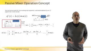
Using trigonometric identities, the output becomes:
S_out(t) = \frac{1}{2} \left[ A_{RF} \cos(2\pi (f_{RF} - f_{LO})t) + A_{RF} \cos(2\pi (f_{RF} + f_{LO})t) \right].
Detailed Explanation
The output signal of the mixer is expressed in terms of trigonometric identities, providing a clear mathematical representation of how the combined signals behave over time. This equation shows that the output signal is a combination of oscillating functions at both the sum and difference frequencies. It's important for understanding how these signals can be represented mathematically, which is crucial for analysis and further processing in RF applications.
Examples & Analogies
Think of this process like a dance where two dancers (the RF and LO signals) move in harmony, sometimes coming together and sometimes moving apart. The performance (output signal) beautifully illustrates the interplay between their movements (oscillations), creating a captivating show (communication signal).
The Role of Nonlinear Devices
Chapter 4 of 5
🔒 Unlock Audio Chapter
Sign up and enroll to access the full audio experience
Chapter Content
Mixers operate based on nonlinear devices (e.g., diodes, transistors) that generate the sum and difference frequencies. The mixer’s nonlinear behavior can be modeled as a combination of harmonic and intermodulation components, which is useful for frequency conversion but can also introduce unwanted spurious signals.
Detailed Explanation
Mixers rely on nonlinear devices, which means that they do not respond proportionately to the input signals. This nonlinearity is essential for generating the new frequencies (the sums and differences), but it can lead to the creation of undesirable additional frequencies known as spurious signals. Therefore, understanding and managing this nonlinear behavior is critical in the design and application of mixers.
Examples & Analogies
Consider a guitarist who bends a string to create unexpected new notes (nonlinear behavior). While this adds uniqueness to the music, it might also introduce sounds that were not intended (spurious signals). In a similar way, mixers can produce both desired output frequencies and some that may not be useful, requiring careful design to control them.
Understanding Conversion Loss and Gain
Chapter 5 of 5
🔒 Unlock Audio Chapter
Sign up and enroll to access the full audio experience
Chapter Content
● Conversion Loss: The conversion loss refers to the difference in power between the input RF signal and the resulting output IF signal. In ideal mixers, this loss is minimal, but real-world mixers exhibit some conversion loss due to inefficiencies in frequency conversion.
● Conversion Gain: In some cases, the mixer may exhibit a conversion gain, meaning the output power is greater than the input RF power.
Detailed Explanation
This chunk discusses two important concepts: conversion loss and gain. Conversion loss is a measure of how much power is lost in the mixing process, which is a common issue in practical applications. Conversely, conversion gain refers to scenarios where the mixer can produce more power in the output signal than what was input. However, conversion gain is less common and not the norm for most mixers. Understanding these terms is key to evaluating a mixer's performance.
Examples & Analogies
Imagine filling a water bottle (the input RF power). If some water spills out as you pour (conversion loss), you end up with less water than you started with. In rare cases, you might find a magic bottle that fills itself while you pour (conversion gain), giving you more water than you had. Knowing how to manage these scenarios helps ensure you get the most out of your mixing process.
Key Concepts
-
Frequency Mixing: The process of combining RF and LO signals to produce new frequencies.
-
Nonlinear Operations: Mixers rely on the nonlinear characteristics of components to generate sum and difference frequencies.
-
Conversion Loss: The power reduction typically experienced when the RF signal is converted to an IF signal.
-
Conversion Gain: The situation where output power is higher than the input RF power, although uncommon.
Examples & Applications
In a typical radio receiver, an RF signal at 100 MHz is mixed with a 10 MHz LO signal, resulting in the sum frequency of 110 MHz and a difference frequency of 90 MHz.
In radar systems, mixers can downconvert high-frequency reflected signals to a lower IF, making detection easier.
Memory Aids
Interactive tools to help you remember key concepts
Rhymes
Mixing is nifty, it changes the show, sum and difference in signals, that's how they flow!
Stories
Imagine two musicians—one playing higher notes (RF) and the other playing lower notes (LO). When they play together, they create beautiful harmonies (sum and difference frequencies) that can be delightful to the ear.
Memory Tools
Remember 'SLO-MIX' for Sum and LO frequencies producing Mixed outputs.
Acronyms
MIX - Mixers Integrate eXcitations (frequencies) from RF and LO.
Flash Cards
Glossary
- Mixer
A device that combines two input signals to produce sum and difference frequencies in RF systems.
- RF Signal
The high-frequency signal that is to be mixed in a mixer.
- Local Oscillator (LO)
A low-frequency signal used to mix with the RF signal to generate intermediate frequencies.
- Sum Frequency
The frequency result of adding the RF signal frequency and LO frequency (f_sum = f_RF + f_LO).
- Difference Frequency
The frequency result of subtracting the LO frequency from the RF signal frequency (f_diff = |f_RF - f_LO|).
- Conversion Loss
The reduction in power that occurs when an RF signal is converted to an intermediate frequency signal in mixers.
- Conversion Gain
The phenomenon where the output power of a mixer exceeds its input RF power, though this is less common.
- Nonlinear Device
A component that does not have a straight-line relationship between input and output, critical in generating mixing products.
- Spurious Signals
Unwanted signals generated during the mixing process that can interfere with desired output signals.
Reference links
Supplementary resources to enhance your learning experience.