
Overview of the SoC Design Flow
Enroll to start learning
You’ve not yet enrolled in this course. Please enroll for free to listen to audio lessons, classroom podcasts and take practice test.
Interactive Audio Lesson
Listen to a student-teacher conversation explaining the topic in a relatable way.
Concept and Specification
🔒 Unlock Audio Lesson
Sign up and enroll to listen to this audio lesson

Welcome, everyone! Let's start with the first phase of the SoC design flow: Concept and Specification. Can anyone tell me why defining specifications is critical at the beginning of the design process?

Because it sets the requirements for the entire project!
Exactly! It ensures that all stakeholders agree on what the final product should achieve. This includes performance, power, and area requirements. Can anyone give me an example of a factor we might analyze during this phase?

We would analyze cost constraints!
Great point! Cost constraints are very important, especially in competitive markets. Remember the acronym **PPA** for Performance, Power, and Area. Let’s summarize: the specification phase sets the foundation for the design by clarifying all requirements.
High-Level Design
🔒 Unlock Audio Lesson
Sign up and enroll to listen to this audio lesson

Now that we have our specifications, let’s move to High-Level Design. What are some key decisions we make in this stage?

We choose the types of processors and memory architecture!
Yes! And don't forget to consider the peripherals as well—like USB and Ethernet. This is where we start to balance our performance against power consumption. Can someone explain why choosing the right processor type is vital?

Because it affects how well the SoC performs its intended tasks!
Absolutely! The right processor choice can vastly influence the capabilities of the SoC. To help remember this stage, think of the acronym **RAMP**: **R**equirements, **A**rchitecture, **M**emory, and **P**eripherals.
RTL Design
🔒 Unlock Audio Lesson
Sign up and enroll to listen to this audio lesson
Next is the RTL Design phase, where we implement the logic of the SoC. What language do we use for coding here?
Verilog or VHDL!
Correct! These hardware description languages let us define the SoC’s behavior. Why is the integration of IP blocks beneficial during this phase?
Because it saves development time since those modules are pre-designed!
Exactly! Using IP cores can streamline our process significantly. Now, let’s remember the term **IP** as **I**ntegrated **P**erformance to reinforce their importance during RTL design.
Verification
🔒 Unlock Audio Lesson
Sign up and enroll to listen to this audio lesson
Now onto the Verification phase, perhaps the most crucial. What types of verification do we conduct?
Functional, formal, and timing verification!
Right! Each type plays a vital role. Can someone explain why timing verification is so important?
Because we need to ensure signals propagate through the chip within the required timing limits.
Exactly! Timing verification ensures that our SoC behaves reliably. A memory aid here is **FIFTY**: **F**unctional, **I**nteroperability, **F**ormal, **T**iming, **Y**ield—reminding us of the different types of verification needed.
Tape-out
🔒 Unlock Audio Lesson
Sign up and enroll to listen to this audio lesson
Finally, let’s discuss Tape-out. This is when the design is sent for fabrication. What does this process involve?
Generating the masks for photolithography!
Correct! Without proper masks, fabrication cannot occur. Can anyone reflect on why this stage is crucial to the entire process of SoC design?
Because it’s the transition from design to physical reality, allowing the project to move forward.
Well said! Tape-out is the culmination of all design efforts and a significant milestone. Remember, we can think of the phrase **FINAL**: **F**abrication, **I**mplementation, **N**etworking, **A**pplications, **L**aunch to encapsulate this phase.
Introduction & Overview
Read summaries of the section's main ideas at different levels of detail.
Quick Overview
Standard
This section details the structured phases of the SoC design flow, emphasizing the importance of each stage—from initial specifications and high-level design to RTL design, synthesis, physical design, verification, and finally, tape-out. Each stage is interlinked and critical for achieving optimal performance and manufacturability.
Detailed
Overview of the SoC Design Flow
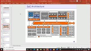
The SoC (System on Chip) design flow is a systematic and iterative process that involves the following key stages:
- Concept and Specification: This initial phase establishes the SoC's requirements, including its architecture and performance goals, which will guide the entire design process.
- High-Level Design (Architectural Design): Architects choose processors, memory architectures, and peripherals, optimizing for performance, power, and area.
- RTL Design: In this critical phase, the actual behavior of the chip is coded in hardware description languages (HDLs) such as Verilog or VHDL, including integrating pre-designed components (IP blocks).
- Synthesis: The RTL code is converted into a gate-level representation, focusing on optimizing for performance and area.
- Physical Design: This phase involves creating a physical layout that can be fabricated, including floorplanning, placing components, and routing connections.
- Verification: Various verification methods ensure that the design meets specifications, including functional, formal, and timing verification.
- Tape-out: The final design is prepared for manufacturing, involving the generation of masks needed for production.
These stages provide a comprehensive understanding of how SoCs are designed and the associated challenges, ensuring prototypes meet both functional requirements and industry standards.
Youtube Videos

Audio Book
Dive deep into the subject with an immersive audiobook experience.
Concept and Specification
Chapter 1 of 7
🔒 Unlock Audio Chapter
Sign up and enroll to access the full audio experience
Chapter Content
The design flow begins with defining the specifications and requirements for the SoC. This stage involves:
- System Architecture Definition: Determining the high-level architecture of the SoC, including the types of processors (e.g., ARM Cortex, RISC-V), memory hierarchy, and the inclusion of peripherals such as sensors, networking modules, or display controllers.
- Requirements Analysis: Identifying the functional, performance, power, area, and cost constraints. This may include deciding on the target application (e.g., mobile, automotive, industrial) and understanding the trade-offs between performance and power consumption.
Detailed Explanation
In this initial stage, the design team defines what the SoC needs to accomplish. This includes creating a high-level architectural framework that specifies the processors to be used, memory configurations, and necessary peripherals. Additionally, a thorough analysis of requirements is done to determine various constraints, such as performance goals, power consumption limits, physical size constraints, and budget considerations. By clearly setting out these specifications, all team members can work towards a common goal, addressing potential issues early on.
Examples & Analogies
Imagine someone planning to build their first home. They start by determining the size of the house, how many rooms they need, and what amenities (like a garage or garden) they want. They also have to consider their budget and the neighborhood they want to live in. Just as these decisions shape the building process, specifications set the direction for what capabilities the SoC must have.
High-Level Design (Architectural Design)
Chapter 2 of 7
🔒 Unlock Audio Chapter
Sign up and enroll to access the full audio experience
Chapter Content
Once the specifications are defined, the next stage is high-level design, where the architectural choices for the SoC are made. This includes:
- Processor Selection: Deciding on the type of CPU, GPU, and any specialized accelerators needed for the application.
- Memory Architecture: Designing the memory subsystem, including on-chip memory (e.g., SRAM, cache) and off-chip memory (e.g., DRAM).
- Peripherals and I/O Interfaces: Deciding on which peripherals to include (e.g., USB, HDMI, Ethernet) and how they interface with the processor and memory.
- Power, Performance, and Area (PPA) Analysis: Analyzing trade-offs between performance, power consumption, and the area occupied by the SoC.
Detailed Explanation
In the high-level design stage, the team makes critical decisions about the architecture of the SoC based on previously defined specifications. They select processors that fit the application needs and design the memory structure for efficient data management. The team also determines which peripherals will be included and how they will connect to the processor. Furthermore, they analyze the trade-offs regarding power consumption, performance, and space on the chip to ensure the design aligns with the outlined goals.
Examples & Analogies
Consider a basketball coach designing a game strategy based on their players' strengths. The coach selects which players to position where, decides on the plays to run based on the strengths of specific players (like a strong shooter or quick defender), and continuously adapts the strategy based on the opposing team's strengths and weaknesses. Similarly, the SoC design team must choose the right components and connections to ensure the chip works efficiently for the targeted application.
RTL Design (Register Transfer Level Design)
Chapter 3 of 7
🔒 Unlock Audio Chapter
Sign up and enroll to access the full audio experience
Chapter Content
At the heart of SoC design is the RTL design phase, where the actual logic of the chip is implemented. This involves writing the logic description of the SoC in hardware description languages (HDLs), such as Verilog or VHDL.
- Designing the Core Logic: Writing RTL code to implement the behavior of the processor, memory controllers, and peripheral components.
- IP Integration: In modern SoC design, using intellectual property (IP) blocks (pre-designed functional modules) is common.
- Bus Architecture: Designing the communication network between different components.
- HDL Simulations: The RTL code is then simulated to verify that the logic behaves as expected.
Detailed Explanation
The RTL design phase focuses on the actual coding of the SoC's functionality using hardware description languages. The team writes the logic that dictates how the chip will function, including how different components like the processor and memory will behave. They can also incorporate pre-designed functional modules (IP blocks) to speed up the design process. Once the RTL code is written, simulations are carried out to verify that all components operate as intended, ensuring the logic matches the planned specifications.
Examples & Analogies
Think of creating a recipe for a new dish. The RTL design is like writing down all the steps and ingredients needed to cook the dish. If a cook uses an already established recipe for a sauce (IP block), they combine it with their unique components to create something new. By performing a test run of the dish (simulation), they check that everything tastes as it should before presenting it for others to enjoy.
Synthesis
Chapter 4 of 7
🔒 Unlock Audio Chapter
Sign up and enroll to access the full audio experience
Chapter Content
Once the RTL code is verified, the design undergoes synthesis, where the RTL description is converted into a gate-level representation. This involves:
- Logic Optimization: The synthesis tool optimizes the logic to meet performance, area, and power requirements.
- Gate-Level Netlist Generation: The tool generates a netlist—a list of logic gates and their connections—that can be implemented in silicon.
Detailed Explanation
Synthesis is the stage where the RTL code transitions from a design blueprint to a more practical format that can be manufactured. Using specialized tools, the logic is optimized based on the defined goals of performance, area, and power consumption. The outcome of this phase is a gate-level netlist, which is a detailed list showing how all the logic gates are interconnected to fulfill the desired functionality.
Examples & Analogies
Consider a team drawing up a detailed architectural plan for a building after it was sketched out in rough forms. The synthesis process is akin to refining the plan to maximize space while ensuring all safety and aesthetic standards are met. By finalizing the layout (netlist), they can move forward to actually construct the building.
Physical Design
Chapter 5 of 7
🔒 Unlock Audio Chapter
Sign up and enroll to access the full audio experience
Chapter Content
After synthesis, the design moves to the physical design phase. This step focuses on converting the gate-level netlist into a physical layout that can be fabricated on silicon.
- Floorplanning: The process of defining the physical layout of the SoC.
- Placement and Routing: The physical design tools place the gates and route the connections between them on the chip.
- Clock Tree Synthesis: Ensuring that the clock signal reaches all parts of the SoC with minimal delay and skew.
- Physical Verification: Ensuring that the layout meets manufacturing requirements.
Detailed Explanation
In the physical design phase, the focus is on the actual representation of the SoC that will be produced. The design is mapped out on silicon: components are laid out spatially (floorplanning), and paths between components are established (placement and routing). The aim is to optimize space while ensuring efficient signal travel. The clock tree synthesis ensures that the necessary timing signals reach all components uniformly. Additionally, physical verification checks proceed to ensure that the layout complies with necessary manufacturing standards.
Examples & Analogies
Imagine organizing a warehouse. After deciding what items to store, you'll need to create a blueprint showing where everything will go. You’ll arrange shelves for optimum access while ensuring that important pathways are clear. Just like in the warehouse, the physical design of an SoC arranges it in a way that ensures it works efficiently when built.
Verification
Chapter 6 of 7
🔒 Unlock Audio Chapter
Sign up and enroll to access the full audio experience
Chapter Content
Verification is one of the most crucial phases in SoC design. It ensures that the design behaves as expected and meets the initial specifications. Verification can be done at different stages of the design process:
- Functional Verification: Ensures that the design performs the required tasks and meets functional requirements.
- Formal Verification: Uses mathematical techniques to prove that the RTL code will function correctly.
- Timing Verification: Ensures that the design meets timing constraints.
- Simulation and Emulation: Simulations are run to check for correctness, performance, and power.
- Hardware Emulation: Implementation on a prototype hardware platform to test functionality.
Detailed Explanation
The verification phase is critical to any SoC design, acting as a safety net to ensure that everything functions as expected. Various methods are utilized, including functional verification to check if the design meets functional requirements, formal verification for mathematical proof of logic correctness, and timing verification to confirm that signals reach their destinations within set time limits. Multiple simulation methods verify the entire design before moving forward, guaranteeing reliability.
Examples & Analogies
Consider a car manufacturer who goes through rigorous testing to assure that the car performs safely and efficiently even before it hits the road. They check for functionality (does it start and drive?), performance (how fast can it go?), and safety (will it withstand an accident?). Just as with cars, verification in SoC design ensures that every feature works properly before reaching consumers.
Tape-out
Chapter 7 of 7
🔒 Unlock Audio Chapter
Sign up and enroll to access the full audio experience
Chapter Content
After successful verification, the design proceeds to the tape-out phase, where the final design is sent to the semiconductor foundry for fabrication. The tape-out process involves generating the masks required for the photolithography process that will be used to etch the design onto the silicon wafer.
Detailed Explanation
The tape-out phase marks the transition from design to actual production. After all verifications are complete and the design is validated, the final design is sent to the foundry where it will be fabricated. It involves generating specialized masks used in the photolithography process to imprint the design onto silicon wafers. This is a crucial step since any errors at this stage can result in significant rework.
Examples & Analogies
Think of tape-out as sending your finalized blueprint to builders who will construct your house. Once the blueprint is sent, they begin the process of building. If everything was done correctly while planning, the construction will reflect the desired outcome perfectly, just like the successful fabrication of an SoC based on a well-prepared design.
Key Concepts
-
Concept and Specification: The foundational stage of defining requirements for SoC design.
-
High-Level Design: Making architectural choices including processor selection and system components.
-
RTL Design: Writing hardware descriptions in HDLs to define functionality.
-
Verification: The process of ensuring design correctness through various testing methods.
-
Tape-out: The final step before manufacturing involving the preparation of design for production.
Examples & Applications
An example of SoC is a smartphone chip that integrates CPU, GPU, and memory on a single chip.
During RTL Design, if a designer uses Verilog to code the processor behavior, they are defining how the processor responds under various conditions.
Memory Aids
Interactive tools to help you remember key concepts
Rhymes
To design a SoC, we must first define, with PPA in mind, our specifications align.
Stories
Once upon a time, in a land of chips, architects crafted specs as tight as a grip. They chose CPUs, and memory wise, to build a SoC that would surely rise!
Memory Tools
RAMP for High-Level Design: Requirements, Architecture, Memory, and Peripherals.
Acronyms
FINAL for Tape-out
Fabrication
Implementation
Networking
Applications
Launch.
Flash Cards
Glossary
- SoC (System on Chip)
An integrated circuit that consolidates all components of an electronic system into a single chip.
- RTL (Register Transfer Level)
A level of abstraction used to describe the operation of a digital electronic system.
- PPA (Performance, Power, Area)
Criteria used to analyze the trade-offs in SoC design.
- IP (Intellectual Property) block
Pre-designed functional modules that can be reused in SoC designs.
Reference links
Supplementary resources to enhance your learning experience.