
Graphical Radial Triangulation
Enroll to start learning
You’ve not yet enrolled in this course. Please enroll for free to listen to audio lessons, classroom podcasts and take practice test.
Interactive Audio Lesson
Listen to a student-teacher conversation explaining the topic in a relatable way.
Understanding Graphical Radial Triangulation
🔒 Unlock Audio Lesson
Sign up and enroll to listen to this audio lesson

Today, we're diving into graphical radial triangulation. Can anyone tell me the purpose of this technique in photogrammetry?

Is it used to accurately position photographs?
Exactly! We use it to ensure the photographs are placed correctly on a map. What tools do you think we might need for this process?

Maybe a ruler and a pencil?

And a mirror stereoscope!
Great answers! These tools help us identify points on the photographs and align them properly. Now, let's move on to how we identify Ground Control Points, or GCPs.
Identifying Control Points
🔒 Unlock Audio Lesson
Sign up and enroll to listen to this audio lesson

The first step in our triangulation is to identify GCPs on the photographs. Why are these points important?

They help us to accurately position and scale our photographs!
Absolutely! Next, we select minor control points, or MCPs. They need to be nearly at the same elevation as our principal point. Can someone tell me why that is?
So they don’t create height discrepancies in our mapping!
Exactly! And we also have to consider their distance from the principal point. The distance should be twice the mean base of the adjoining photographs. Let’s repeat that for clarity: twice the mean base! Can anyone explain what the mean base is?
I think it's the average distance between two photographs!
Drawing Radial Directions
🔒 Unlock Audio Lesson
Sign up and enroll to listen to this audio lesson
Now that we have our MCPs and LCPs, the next step is to draw radial directions from the principal point to all control points. Why do we do this?
To create a visual representation and connect all the important points!
Right! Drawing these radials helps ensure that when we transfer points to other photographs, everything will align correctly. What challenges do you think we might encounter during this process?
Differences in elevation or scale between the photographs might cause issues.
That’s correct! We need to address scale variations due to changes in altitude during flight. This is where graphical triangulation becomes critical. Let’s take a look at how to adjust for these variations.
Scaling Photographs
🔒 Unlock Audio Lesson
Sign up and enroll to listen to this audio lesson
When we scale our photographs, what do we aim for?
To have them all at the same scale!
Exactly! We bring all photographs to a common scale based on our average photo scale. How might we achieve that?
By projecting and adjusting the scales according to GCP locations!
Well said! It involves plotting all known control data and using lateral control points to achieve a precise fit of the photographs. Can someone think of the advantages this technique offers?
It helps reduce errors and creates a more accurate final map!
Absolutely! A common scale across the photographs ensures fewer discrepancies and greater reliability in our maps.
Finalizing the Map
🔒 Unlock Audio Lesson
Sign up and enroll to listen to this audio lesson
After scaling and thoroughly checking our points, what should we do next?
Prick through the tracing sheet to mark all the control points!
Correct! And what’s our goal with these prick marks?
To ensure all ground control points accurately fall over their plotted positions!
Yes! Now, this step is crucial. If there are any discrepancies, what should we be prepared to do?
We might need to rescale some strips or use intermediate tie points!
Exactly right! Final adjustments help us create a seamless and accurate map. Well done, everyone!
Introduction & Overview
Read summaries of the section's main ideas at different levels of detail.
Quick Overview
Standard
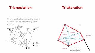
This section outlines the method of graphical radial triangulation using simple tools such as mirror stereoscopes, rulers, and tracing sheets, detailing the steps to identify control points and adjust scales for aerial photography.
Detailed
Graphical Radial Triangulation
Graphical radial triangulation is a photogrammetric technique that utilizes basic instruments to establish control points and rectify photographic scales. The essential steps of this process revolve around identifying Ground Control Points (GCPs) and manipulating photographs through stereoscopic methods. The process begins with the organization of photographs in strips, where the principal point of each photograph is defined. Subsequently, minor control points (MCPs) and lateral control points (LCPs) are identified and transferred to adjacent photographs. A crucial aspect of this triangulation method is to address scale variations that stem from differences in terrain elevation and flying height, ensuring all photographs can be represented at a common scale. This meticulous process aims to create a uniform map from the various photographs to alleviate discrepancies caused by azimuthal errors or elevation variations. By the end of this process, each photograph will be accurately plotted on a transparent tracing sheet, ensuring precision in mapping results.
Youtube Videos


Audio Book
Dive deep into the subject with an immersive audiobook experience.
Instruments for Graphical Radial Triangulation
Chapter 1 of 11
🔒 Unlock Audio Chapter
Sign up and enroll to access the full audio experience
Chapter Content
Graphical radial triangulation is performed with simple instruments, such as mirror stereoscope, a ruler, a pencil and a tracing sheet.
Detailed Explanation
Graphical radial triangulation is a method that uses basic tools to align and measure positions based on photographs. The instruments mentioned include a mirror stereoscope for viewing photographs in 3D, a ruler for measuring distances, a pencil for marking important points, and a tracing sheet for plotting and transferring data.
Examples & Analogies
Think of it like putting together a jigsaw puzzle. You need specific tools (your hands, a table) to fit pieces together accurately and see the full picture clearly.
Step 1: Photograph Layout and GCP Identification
Chapter 2 of 11
🔒 Unlock Audio Chapter
Sign up and enroll to access the full audio experience
Chapter Content
The photographs are laid out in strips and all GCPs are identified on the photographs and their numbers marked on the photographs.
Detailed Explanation
In this step, photographs are organized in a sequence called strips. Ground Control Points (GCPs) are critical points on the ground whose locations are known. By marking these points on the photographs, the process ensures accurate interpretation of the terrain when analyzing the images.
Examples & Analogies
Imagine preparing a treasure map where you have to mark locations of treasures accurately. Without clearly identifying where each treasure is on the map, it would be hard to find them!
Step 2: Identifying Principal Points
Chapter 3 of 11
🔒 Unlock Audio Chapter
Sign up and enroll to access the full audio experience
Chapter Content
The principal point is obtained for each photograph. The principal points are then stereoscopically transferred to the adjoining photographs as conjugate principal points.
Detailed Explanation
The principal point is a central reference point on each photograph that is essential for accurate positioning. By transferring this point between adjoining photographs, it helps maintain consistency in measurements and relations between different images.
Examples & Analogies
Think of it as a common meeting point for friends. If everyone knows where to meet, it’s easier for them to find each other regardless of where they are.
Step 3: Selection of Minor Control Points
Chapter 4 of 11
🔒 Unlock Audio Chapter
Sign up and enroll to access the full audio experience
Chapter Content
Now two points, called minor control points (MCPs), also called pass points or wing points, are selected on both sides of the principal point of photo...
Detailed Explanation
MCPs are additional reference points chosen near the principal point to aid in accurate plotting. Several conditions ensure they are suitable for this role, including being at the same elevation as the principal point and positioned correctly in relation to adjoining photographs.
Examples & Analogies
Consider a road with guideposts. The principal point is like the main junction, and the minor control points are like the guideposts along the road that help guide travelers and ensure they are on the right path.
Step 4: Stereoscopic Transfer of MCPs
Chapter 5 of 11
🔒 Unlock Audio Chapter
Sign up and enroll to access the full audio experience
Chapter Content
The MCPs are selected and transferred stereoscopically to adjoining photographs.
Detailed Explanation
This step involves using a stereoscope to ensure that the selected MCPs are accurately plotted on neighboring photographs, enhancing the spatial relationships depicted.
Examples & Analogies
Similar to aligning pieces when building a LEGO structure. Ensuring each piece fits perfectly means that the whole structure will be stable and look correct.
Step 5: Selection of Lateral Control Points
Chapter 6 of 11
🔒 Unlock Audio Chapter
Sign up and enroll to access the full audio experience
Chapter Content
The lateral control points (LCPs) are selected in the centre of lateral overlaps of adjacent strips...
Detailed Explanation
LCPs serve as important reference points located at overlaps between strips of photographs, providing a connection and continuity across images. This helps in stitching together larger parts of the map accurately.
Examples & Analogies
Consider the way dancers rehearse a routine. LCPs are like markers on the floor that guide where each dancer needs to be positioned to maintain formation and flow.
Step 6: Drawing Radial Directions
Chapter 7 of 11
🔒 Unlock Audio Chapter
Sign up and enroll to access the full audio experience
Chapter Content
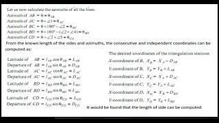
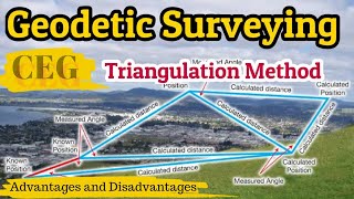
The radial directions from the principal point to all minor control, lateral control and ground control points appearing on the photograph are drawn, through the points.
Detailed Explanation
In the final step, radial lines are drawn from the principal point to all identified control points on the photograph. This process visually indicates the relationships and directions to these key points, facilitating accurate mapping and measurements.
Examples & Analogies
Imagine drawing lines on a treasure map from a 'You Are Here' marker to various landmarks (mountains, rivers) that will guide you. The lines help you to navigate efficiently to your destination.
Addressing Scale Variations
Chapter 8 of 11
🔒 Unlock Audio Chapter
Sign up and enroll to access the full audio experience
Chapter Content
Due to elevation differences of terrain and variations in the flying height of aircraft, the scale of photographs generally varies considerably...
Detailed Explanation
In photogrammetry, variations in scale can lead to inaccuracies. Therefore, a common scale is established through graphical triangulation, ensuring all photographs fit together correctly.
Examples & Analogies
Think of it like adjusting all your photos to the same filter on social media so they look consistent. This way, everything matches and appears orderly.
MCP Plotting on Transparent Sheets
Chapter 9 of 11
🔒 Unlock Audio Chapter
Sign up and enroll to access the full audio experience
Chapter Content
Each strip is plotted on a transparent sheet to facilitate the drawing. The photographs are laid out in their correct relative directions...
Detailed Explanation
Plotting on transparent sheets allows for easy viewing and manipulation of the base photographs. It ensures that all elements can be aligned precisely as needed, maintaining the correct relationships between points.
Examples & Analogies
Imagine laying a clear sheet over a picture to trace over key details. This ensures you capture all necessary elements without losing track of the original image.
Scaling Plots to a Uniform Scale
Chapter 10 of 11
🔒 Unlock Audio Chapter
Sign up and enroll to access the full audio experience
Chapter Content
The MCPs of different strips are at different scales. To bring all of them to the same scale, a projection is made...
Detailed Explanation
When multiple strips are used, they often have varying scales due to different elevations or aircraft heights. By projecting and adjusting these scales, all strips can be aligned to a common standard for consistent analysis.
Examples & Analogies
Similar to resizing images in a collage to ensure every picture is the same size, enhancing the overall aesthetic coherence of the layout.
Final Adjustments and Quality Control
Chapter 11 of 11
🔒 Unlock Audio Chapter
Sign up and enroll to access the full audio experience
Chapter Content
After scaling all the points of minor control plots, these points are pricked through the tracing sheet...
Detailed Explanation
After the points are scaled accurately, they are transferred carefully onto the plotting sheet, ensuring that all points align as expected. This step is essential in verifying the accuracy of the triangulation process.
Examples & Analogies
Think of it like a final proofreading step on an essay. You're double-checking every detail to ensure everything is in its right place before submission.
Key Concepts
-
Graphical Radial Triangulation: A method used in photogrammetry for positioning photographs.
-
Ground Control Points (GCPs): Dependable points used to correlate photographs with real-world locations.
-
Minor Control Points (MCPs): Additional control points used to improve the accuracy of the triangulation.
-
Lateral Control Points (LCPs): Points serving as connection references between photographic strips.
Examples & Applications
An example of identifying GCPs involves marking physical landmarks visible in all photographs, ensuring alignment.
In practice, MCPs might be located at known elevations near a principal point to establish consistency in mapping.
Memory Aids
Interactive tools to help you remember key concepts
Rhymes
To triangulate, you must create, Control points will help you relate.
Stories
Imagine a photographer flying over landscapes, marking key spots on a map, ensuring that every image aligns seamlessly in their aerial gallery.
Memory Tools
G - Ground, M - Minor, L - Lateral; Remember the Three Control Points for Triangulation!
Acronyms
GML - Ground, Minor, Lateral for all control points needed!
Flash Cards
Glossary
- Ground Control Points (GCPs)
Fixed points on the ground used to georeference photographs.
- Minor Control Points (MCPs)
Control points used to assist in ensuring the accuracy of the principal point.
- Lateral Control Points (LCPs)
Points used in the center of lateral overlaps of adjacent strips connecting different strips.
- Radial Directions
Lines drawn from the principal point to various control points to establish connections.
Reference links
Supplementary resources to enhance your learning experience.