
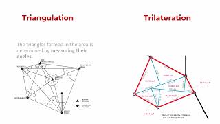
Steps for graphical radial triangulation
Enroll to start learning
You’ve not yet enrolled in this course. Please enroll for free to listen to audio lessons, classroom podcasts and take practice test.
Interactive Audio Lesson
Listen to a student-teacher conversation explaining the topic in a relatable way.
Introduction to Graphical Radial Triangulation
🔒 Unlock Audio Lesson
Sign up and enroll to listen to this audio lesson

Today, we'll explore graphical radial triangulation! This technique helps us align aerial photographs accurately. Can anyone tell me why it's important to have accurate photographs in mapping?

It's important for creating realistic maps that reflect the actual terrain!
Exactly! Accurate maps are essential for navigation and planning. Let's delve into how we can achieve this with basic tools like a mirror stereoscope, a ruler, and a tracing sheet.

What are GCPs?
Great question! GCPs, or Ground Control Points, are identifiable points on the ground whose positions are known. They serve as reference points for our photographs.
Identifying Control Points
🔒 Unlock Audio Lesson
Sign up and enroll to listen to this audio lesson

Now, let’s discuss how to select control points. The first steps involve laying out the photographs and identifying GCPs. Can anyone guess why we mark these points?

To ensure we can find them easily later on?
Exactly! Marking helps in accurate plotting. We also use Minor Control Points, or MCPs. They should be chosen at a particular distance and elevation that relates to the principal point.

Why do elevation and distance matter?
Good point! Ensuring MCPs are at similar elevations helps reduce errors in 3D modeling. Remember: 'Higher is drier, but placement is key!'
Stereoscopic Transfer and Drawing Radials
🔒 Unlock Audio Lesson
Sign up and enroll to listen to this audio lesson
Once GCPs and MCPs are marked, we go to stereoscopic transfers. Can anyone explain what stereoscopic mean in this context?
Isn't it creating an illusion of depth from two images?
Exactly! We transfer points from one photograph to another, helping us visualize depth. After that, we draw radial directions to all control points. What’s the benefit of this?
It helps in aligning the photographs accurately!
Right! By drawing these radials, we can plot everything correctly and prepare for scaling.
Scaling and Common Scale Adjustment
🔒 Unlock Audio Lesson
Sign up and enroll to listen to this audio lesson
To finalize our mapping, let's talk about scaling. We often encounter variations in photograph scales due to elevation differences. How do we normalize these?
By ensuring all photographs are adjusted to a common scale?
Exactly! Adjusting to a common scale prevents distortions in our final output. Remember to always be aware of the flying height and elevation when scaling. Can anyone think of an acronym to remember the critical steps in this process?
How about 'G-R-S' for 'GCPs, Radials, Scales'?
Great mnemonic! G-R-S is a simple way to remember the key steps in our triangulation process.
Final Plot and Error Minimization
🔒 Unlock Audio Lesson
Sign up and enroll to listen to this audio lesson
Finally, we plot our strips and make adjustments. Why do we need to check for errors in our mapping process?
To ensure our map is accurate and reliable?
Correct! Any discrepancies can lead to significant errors in mapping. Let’s summarize key concepts: Control Points, Stereoscopic Transfers, and Scaling.
This sounds really important for achieving accurate results!
Introduction & Overview
Read summaries of the section's main ideas at different levels of detail.
Quick Overview
Standard
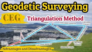
This section outlines the steps involved in graphical radial triangulation, including the selection of control points, the process of stereoscopic alignment of photographs, and the establishment of a common scale for accurate mapping of terrain. It emphasizes the practical approach using basic tools like a mirror stereoscope and explains the significance of careful point selection to minimize errors.
Detailed
Detailed Summary of Graphical Radial Triangulation
Graphical radial triangulation is a photogrammetric technique utilized in mapping and aerial photography. This process employs essential tools such as a mirror stereoscope, ruler, pencil, and tracing sheets, making it accessible for users without advanced equipment. The procedure begins by laying out photographs in strips, identifying Ground Control Points (GCPs) on them, and marking these points for later reference. The principal point of each photograph is identified and transferred to adjacent photographs as conjugate principal points.
Subsequently, two Minor Control Points (MCPs), or wing points, are selected near the principal point, ensuring they meet specific criteria related to elevation and distance. These points are also stereoscopically transferred to neighboring images. Lateral Control Points (LCPs) are chosen within the overlaps of adjacent strips to serve as connections between different strips, further enhancing alignment and accuracy.
Radial directions from the principal point to all control points are then drawn, culminating in a detailed layout of the photographic strip. This method also addresses varying scales of photographs due to elevation differences and flying heights, ensuring that all points are adjusted to a common scale via graphical triangulation. Key to this process is the careful selection of MCPs to minimize cumulative azimuth errors, thereby achieving an accurate map representation.
The systematic nature of graphical radial triangulation not only aids in the alignment of images but also in ensuring that ground control points are adjusted correctly to enable precise mapping. The underlying principle of transferring elevation data accurately through selected control points emphasizes the importance of accurate measurements in photogrammetry.
Youtube Videos


Audio Book
Dive deep into the subject with an immersive audiobook experience.
Introduction to Graphical Radial Triangulation
Chapter 1 of 10
🔒 Unlock Audio Chapter
Sign up and enroll to access the full audio experience
Chapter Content
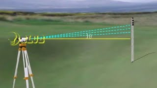
Graphical radial triangulation is performed with simple instruments, such as mirror stereoscope, a ruler, a pencil and a tracing sheet.
Detailed Explanation
Graphical radial triangulation is a technique used to create three-dimensional representations from aerial photographs. It utilizes basic tools like a mirror stereoscope to visualize depth, along with instruments such as a ruler and pencil to make precise measurements. A tracing sheet is used to overlay information from multiple photographs, helping to establish the relationship between the images.
Examples & Analogies
Think of this process like piecing together a 3D puzzle. Each aerial photograph represents a puzzle piece that, when combined with others using simple tools, reveals a detailed and accurate representation of the landscape.
Step 1: Layout and Identification
Chapter 2 of 10
🔒 Unlock Audio Chapter
Sign up and enroll to access the full audio experience
Chapter Content
The photographs are laid out in strips and all GCPs are identified on the photographs and their numbers marked on the photographs.
Detailed Explanation
In this step, the aerial photographs are arranged systematically in strips, making it easier to analyze and cross-reference the images. Ground Control Points (GCPs), which are specific known locations on the ground that correspond to points on the photograph, are marked on each photograph. This helps ensure that the triangulation process is accurate.
Examples & Analogies
Imagine organizing photos from a family vacation in a scrapbook by location. Each photo represents a different scene, and identifying the places (like landmarks) ensures you can tell the story accurately.
Step 2: Establish Principal Points
Chapter 3 of 10
🔒 Unlock Audio Chapter
Sign up and enroll to access the full audio experience
Chapter Content
The principal point is obtained for each photograph. The principal points are then stereoscopically transferred to the adjoining photographs as conjugate principal points.
Detailed Explanation
The principal point is the central reference point of an image where the camera's optical axis intersects the photograph. This step involves determining the principal point for each photo and then using stereoscopic techniques to transfer this information to neighboring photos. This creates a cohesive spatial framework for the analysis.
Examples & Analogies
It's like using a center point on a map to guide you to adjacent areas. By establishing a reference point, you ensure that your coordinates align correctly with your surroundings, much like ensuring street signs point to the same main street.
Step 3: Selecting Minor Control Points
Chapter 4 of 10
🔒 Unlock Audio Chapter
Sign up and enroll to access the full audio experience
Chapter Content
Now two points, called minor control points (MCPs), also called pass points or wing points, are selected on both sides of the principal point of photo, at about 2 cm from the upper and lower edge of the photograph, fulfilling the following conditions: a. The two points should be as nearly at the same elevation as the principal point. b. The points should be at a distance from the principal point, which is equal to twice the mean base of the adjoining photographs. c. The points should lie approximately on the bisector of the base angle on either side, and d. The point should serve as lateral point as well.
Detailed Explanation
In this step, minor control points are chosen close to the principal point to improve the accuracy of the triangulation. These points must be at similar elevations to ensure reliable measurements. Their placement follows several criteria to maintain geometric relationships among the photographs, making them essential for effective triangulation.
Examples & Analogies
Think about positioning yourself at a concert. If you're trying to capture the best audio from different instruments, choosing positions at equivalent distances (not too high or low) provides balanced sound quality, similar to how even minor variations can affect triangulation accuracy.
Step 4: Transferring MCPs
Chapter 5 of 10
🔒 Unlock Audio Chapter
Sign up and enroll to access the full audio experience
Chapter Content
The MCPs are selected and transferred stereoscopically to adjoining photographs.
Detailed Explanation
After selecting the minor control points, these points are transferred to adjacent photographs using stereoscopic methods. This process helps in maintaining geometric consistency across various photos, ensuring the points align correctly when the images are overlaid.
Examples & Analogies
Imagine marking the same point on multiple identical maps. By making sure each mark aligns, you ensure that whoever uses the maps can accurately find the same locations, just like maintaining alignment across photographs.
Step 5: Selecting Lateral Control Points
Chapter 6 of 10
🔒 Unlock Audio Chapter
Sign up and enroll to access the full audio experience
Chapter Content
The lateral control points (LCPs) are selected in the centre of lateral overlaps of adjacent strips to serve as connecting points between different the strips. These LCPs are selected at least at the beginning and the end of the strip and on every third photo of the strip. These are then stereoscopically transferred to photographs of adjoining strips.
Detailed Explanation
Lateral control points provide connections between different photographic strips. By selecting LCPs at strategic locations, such as the start and end of each strip and at regular intervals, the triangulation process gains more accuracy. These points are then transferred stereoscopically to ensure connectivity between the strips.
Examples & Analogies
It's like connecting train tracks: if you have secure connection points (the LCPs), the trains can smoothly travel between different sectors of the route without misalignment.
Step 6: Drawing Radial Directions
Chapter 7 of 10
🔒 Unlock Audio Chapter
Sign up and enroll to access the full audio experience
Chapter Content
The radial directions from the principal point to all minor control, lateral control and ground control points appearing on the photograph are drawn through the points. A photograph on completion of the above process looks as given in Figure 4.26c.
Detailed Explanation
In this step, lines called radial directions are drawn from the principal point to all identified control points. This visualization helps in understanding the spatial relationships among the control points, enhancing the triangulation process's clarity and precision.
Examples & Analogies
Think of this as a spider web being woven. Each radial direction represents a silk strand connecting the central hub of the web (the principal point) to various points around it, showcasing how everything is interconnected.
Adjusting for Scale Differences
Chapter 8 of 10
🔒 Unlock Audio Chapter
Sign up and enroll to access the full audio experience
Chapter Content
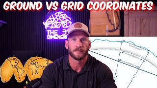
Due to elevation differences of terrain and variations in the flying height of aircraft, the scale of photographs generally varies considerably. The photographs of a strip are required to be brought to a common scale through graphical triangulation.
Detailed Explanation
Because photography conditions can vary significantly due to altitude and terrain, this step ensures that all photographs are adjusted to a common scale. This standardization is crucial for the accuracy of the final mapping or analysis.
Examples & Analogies
Consider adjusting the settings of your camera to compensate for varying light conditions. Just as you would want a consistent exposure for even photographs, having a uniform scale is essential for cohesive mapping.
Preparation of Plots
Chapter 9 of 10
🔒 Unlock Audio Chapter
Sign up and enroll to access the full audio experience
Chapter Content
Each strip is plotted on a transparent sheet to facilitate the drawing. The photographs are laid out in their correct relative directions so that the plotting is carried out in the right direction.
Detailed Explanation
Here, each strip is carefully plotted while ensuring each photograph is oriented correctly. Using transparent sheets allows for easy layering, ensuring that the subsequent drawings reflect actual geographical orientations.
Examples & Analogies
Think of creating an elaborate cake: you layer frosting and decorations carefully to maintain order and appearance. Similarly, plotting photographs requires precision to accurately represent the geographical layout.
Scaling and Final Adjustments
Chapter 10 of 10
🔒 Unlock Audio Chapter
Sign up and enroll to access the full audio experience
Chapter Content
The MCPs of different strips are at different scales. To bring all of them to the same scale, a projection is made. Normally, in graphical method, scale of survey is nearly the same as the average scale of photographs.
Detailed Explanation
This final adjustment focuses on ensuring that all control points across varying strips are scaled uniformly. By projecting the different scales into a common format, consistency and accuracy are achieved in the final output.
Examples & Analogies
Consider mixing different colored paints to arrive at a single shade. You want all colors to blend evenly to create a harmonious result; similarly, standardizing scales helps yield a coherent final product.
Key Concepts
-
Graphical Radial Triangulation: A technique for aligning aerial photographs using GCPs and MCPs.
-
Control Points: Specific points selected to aid in the triangulation process.
-
Common Scale Adjustment: Process of ensuring all photographs maintain a uniform scale for accurate mappings.
Examples & Applications
Using GCPs, students marked the necessary control points on a set of aerial photographs, ensuring proper identification for subsequent triangulation steps.
Students practiced drawing radial lines from principal points to GCPs on paper to visualize the triangulation process.
Memory Aids
Interactive tools to help you remember key concepts
Rhymes
In mapping, we play a tough game, GCPs and MCPs are the points to name.
Stories
A photographer named Sam ventured high above the landscape, using GCPs to anchor his planes, ensuring every photo fell into place, forming a beautiful map of grace.
Memory Tools
G-R-S stands for Ground Control, Radial Lines, and Scaling in triangulation.
Acronyms
To Remember ‘MCP’, think of ‘Minor Closer Points’!
Flash Cards
Glossary
- GCPs
Ground Control Points - identifiable points on the ground used as reference for mapping.
- MCPs
Minor Control Points - points selectednear the principal point for accurate triangulation.
- Radial Lines
Lines drawn from the principal point to control points used for alignment.
- Stereoscope
An optical instrument for viewing two photographs in three dimensions.
- Common Scale
A uniform scale applied to all photographs for accuracy in mapping.
Reference links
Supplementary resources to enhance your learning experience.