
Small Signal Equivalent Circuit
Enroll to start learning
You’ve not yet enrolled in this course. Please enroll for free to listen to audio lessons, classroom podcasts and take practice test.
Interactive Audio Lesson
Listen to a student-teacher conversation explaining the topic in a relatable way.
Introduction to Small Signal Equivalent Circuits
🔒 Unlock Audio Lesson
Sign up and enroll to listen to this audio lesson

Today we will learn about small signal equivalent circuits, which are crucial for analyzing amplifiers. Can anyone tell me what a small signal model is?

Is it a simplified version of the circuit that focuses on small variations around the quiescent point?
Exactly! It's about understanding how circuits behave for small input signals. It allows us to linearize the circuit and analyze its frequency response. Remember, when we refer to quiescent points, we’re talking about where the circuit operates at rest.

What role does the small signal equivalent circuit play in amplifiers?
Great question! It helps us simplify complex amplifier circuits, allowing us to calculate gain, bandwidth, and cutoff frequencies more easily.

So, if I understand correctly, we're replacing all the active components with models that represent their behavior?
Correct! That’s a crucial step in creating the small signal equivalent model. Let’s summarize today’s key points: the small signal model linearizes the circuit around the quiescent point, facilitating easier calculations of gain and frequency response.
Analyzing the Common Source Amplifier
🔒 Unlock Audio Lesson
Sign up and enroll to listen to this audio lesson

Now, let’s look at the common source amplifier circuit. What components do we use in its small signal equivalent model?

I think we replace the transistor with its small signal model and add in the resistances and capacitors.
That's right! We use the transconductance model for the transistor. Remember, transconductance 'g' multiplied by the gate-to-source voltage gives us the current flowing through the model.
How do we calculate the gain in this model?
The voltage gain is expressed as A = -g × R, where 'R' is the load resistance connected at the output. Don’t forget, the negative sign indicates phase inversion.
Are there specific cutoff frequencies we need to be aware of?
Yes! The lower cutoff frequency comes from the interaction of C1 and R1, while the upper cutoff frequency depends on RL and CL. These are crucial for understanding the frequency response of the amplifier.
Can you summarize what we've learned about the common source amplifier?
Absolutely! We learned that the common source amplifier uses a small signal model for analysis. We determine gain through the transconductance model and identify cutoff frequencies that affect frequency response.
Understanding the Frequency Response
🔒 Unlock Audio Lesson
Sign up and enroll to listen to this audio lesson
Now, let's discuss frequency response. Can anyone explain what frequency response means in the context of amplifiers?
I think it tells us how the amplifier performs across different frequencies, right?
Exactly! The frequency response indicates the gain of the amplifier at various frequencies, which helps us understand its performance in different applications.
What factors influence the frequency response?
Several factors, including the values of the resistors and capacitors in the circuit, dictate the cutoff frequencies. The lower cutoff frequency determines how low the input signal can effectively be amplified, while the upper cutoff frequency defines the signal limits on the higher end.
So, a good amplifier should have a wide bandwidth to handle a range of signals?
Yes! The ideal situation is to have a flat response in the mid-frequency range, which allows the amplifier to handle a variety of signals without distortion.
Can we visualize this with Bode plots?
Absolutely! Bode plots visually represent the gain and phase shift against frequency. Key takeaway: understanding frequency response helps in designing effective amplifiers.
Introduction & Overview
Read summaries of the section's main ideas at different levels of detail.
Quick Overview
Standard
In this section, the small signal equivalent circuit is explored through its application in common source and common emitter amplifiers. The section highlights the process of converting an amplifier circuit into a small signal model to facilitate understanding of frequency response, cutoff frequencies, and gain calculations.
Detailed
Detailed Summary of Small Signal Equivalent Circuit
In this section, we delve into the small signal equivalent circuits that form the backbone for analyzing common source (CS) and common emitter (CE) amplifiers. The small signal model allows us to simplify complex circuits into manageable forms by replacing components with their respective models. The essence of the small signal equivalent circuit is that it captures the relevant AC characteristics of the circuit around a particular operating point (also known as the quiescent point). This approach is valuable for evaluating frequency response and determining cutoff frequencies in amplifier design.
Frequency Response of Amplifiers
The theoretical underpinnings begin with the acknowledgment that amplifiers can be modeled by generalized C-R (capacitor-resistor) and R-C (resistor-capacitor) circuits. The output signals are expressed in terms of voltage and current relationships established by transconductance and resistance parameters.
The common source amplifier circuit includes components such as active devices and passive elements. By replacing the specific transistor with its small signal model—especially voltage and current relationship representations—the circuit is considerably simplified. The critical parameters include the voltage gain (A) defined by the relation: A = -g × R, with 'g' representing transconductance and 'R' the load resistance.
Lower and upper cutoff frequencies emerge from the interactions of capacitors and resistors in the circuits, contributing to the overall frequency response. This frequency response reveals how the amplifier reacts over a range of frequencies, leading to insights about gain stability and cutoff points. Consequently, determining R and C values becomes essential in securing optimal performance parameters in amplifier design.
Understanding these dynamics not only assists in theoretical model development but also lays out the pathway for practical designs and applications in electronics.
Youtube Videos

Audio Book
Dive deep into the subject with an immersive audiobook experience.
Overview of the Small Signal Equivalent Circuit
Chapter 1 of 6
🔒 Unlock Audio Chapter
Sign up and enroll to access the full audio experience
Chapter Content
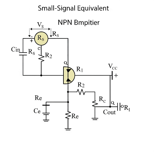
So, say to start with we do have common source amplifier and the circuit is given here. The circuit is given here for your reference and if you see here we do have the main part main amplifier here and then, we are feeding the signal through this capacitor called say C . At the output we are observing the signal after removing the DC part through the C . In addition to that, it may have some capacitive load coming from the next subsequent circuit. So, let you call this is C .
Detailed Explanation
The small signal equivalent circuit is a simplified representation of an amplifier circuit, in which we consider only the AC signals while ignoring any DC components. In this example, we focus on a common source amplifier, which is typically used in various electronic applications. The input signal is first fed to the amplifier through a capacitor (denoted as C), which blocks any DC voltage and allows only AC signals to pass. The output signal is also affected by a capacitor (denoted as C) that may come from the next stage of the circuit. These capacitors play a crucial role in coupling signals across different stages in an amplifier.
Examples & Analogies
Imagine you are listening to music on your phone but want to prevent your phone from charging while listening. The capacitor acts like a gatekeeper—allowing the music (AC signals) to flow through while blocking any charging currents (DC signals). This ensures that the sound remains unaffected by any direct current that might distort the audio.
Defining the Small Signal Model
Chapter 2 of 6
🔒 Unlock Audio Chapter
Sign up and enroll to access the full audio experience
Chapter Content
What we obtained in our previous discussion we say that at the middle, at the middle we got the main amplifier circuit and here of course, it is the small signal equivalent circuit; where, V it is V node, it is AC ground and the transistor it is getting replaced by its small signal model which is voltage dependent current source called i . And its expression it is given by transconductance g × v . v is the voltage appearing across gate to source of the transistor. So, this is the v .
Detailed Explanation
In this part, we transition from the actual amplifier to its small signal equivalent model. We replace the transistor in our circuit with its small signal representation, which acts as a voltage dependent current source. The output current (denoted as i) generated by this model is proportional to the transconductance (g) and the voltage (v) across the gate-source terminals of the transistor. This simplification allows us to analyze the small signal behavior without dealing with the complexities of the actual device.
Examples & Analogies
Think of this concept like a dimmer switch for lights. The amount of light (output current) depends on how much you turn the dimmer (gate-source voltage). This relationship allows you to control the light effectively, similar to how we control the output current based on the small signal equivalent parameters of the transistor.
Thevenin Equivalent Circuits
Chapter 3 of 6
🔒 Unlock Audio Chapter
Sign up and enroll to access the full audio experience
Chapter Content
So, based on this v, we are getting this current and then that current it is flowing through this R and then, of course, we are getting a voltage here. Note that still this is not on equivalent, but it can be easily converted into Thevenin equivalent, namely we can make the amplifier which is having a gain of ‒ g × R .
Detailed Explanation
Here, we observe that the current generated from the voltage across the gate-source terminals flows through a resistor (R), producing an output voltage. The concept of Thevenin's theorem is introduced, which allows us to represent complex circuits with simpler equivalent circuits. In this case, we can replace our amplifier circuit with a Thevenin equivalent that has a specific gain determined by the negative product of the transconductance (g) and resistor (R). This simplification is critical for understanding the behavior of our circuit in analysis and design.
Examples & Analogies
Imagine you are studying a multi-layer cake that looks very complicated. But if you focus on one layer at a time and describe it simply (like Thevenin's theorem), you can grasp the overall structure more easily. The Thevenin equivalent allows engineers to work with complex circuits in a simpler, manageable manner, understanding their behavior layer by layer.
Forming the C-R and R-C Circuits
Chapter 4 of 6
🔒 Unlock Audio Chapter
Sign up and enroll to access the full audio experience
Chapter Content
Likewise, input side again this two part these two resistors you can translate into equivalent resistance here, which it will be R ⫽ R . So, what we can see here that C ; this C . So, this is the C and then, this R which is R ⫽ R , they are forming one C-R circuit.
Detailed Explanation
In the small signal equivalent circuit, we identify the resistors and capacitors that contribute to the overall equivalent resistance and capacitance. On the input side, two resistors are combined to yield an equivalent resistance, while on the output side, certain resistors and capacitors combine to form a C-R circuit. This combination of components allows us to analyze how the circuit responds to changes in frequency, as the arrangement of capacitors and resistors influences the amplifier's frequency response characteristics.
Examples & Analogies
Think of two different paths leading to the same destination. Each path (resistor) affects how quickly you can get there (impedance) depending on whether you take the faster route (lower resistance) or a slower more scenic route (higher resistance). Similarly, capacitors in the circuit influence how signals are combined and processed, affecting the amplifier's performance.
Capacitive Effects in Amplifier Response
Chapter 5 of 6
🔒 Unlock Audio Chapter
Sign up and enroll to access the full audio experience
Chapter Content
This the C-R circuit is getting formed here and then, output resistance which is R and then this C along with this C coming in series, they are these two are farming another circuit which is of course, this is R-C circuit. And this capacitor value, it is it is basically C ⫽ C and its expression it is sorry, this is 2 L in series; this is in series.
Detailed Explanation
In this section, we recognize that the combination of capacitors and resistors forms specific types of filters recognized in the frequency domain. We discuss the formation of both C-R and R-C circuits, which can be analyzed for their effects on the gain and frequency response of the amplifier. When capacitors are arranged in series, their values combine in specific expressions, affecting how they will influence the overall response of the amplifier in various frequency ranges.
Examples & Analogies
Consider a swimming pool with different depths. If the presence of children (capacitors) jumping into the shallow part (C-R circuit) or deep end (R-C circuit) creates waves, those waves represent frequency response. Depending on how deep (the capacitance values) and how wide (the resistance values) the pool is, the behavior of the waves (signal response) changes significantly in amplitude and frequency characteristics, just like how an amplifier responds to input signals.
Frequency Response and Amplifier Design
Chapter 6 of 6
🔒 Unlock Audio Chapter
Sign up and enroll to access the full audio experience
Chapter Content
So, what we are getting here? It is that the amplifier, it can be translated into that unified model which we have discussed just now, before the short break; where, it is having C , then R and then across this R the voltage it is v and that v , it is generating a voltage in which is whatever ‒ g × R time times this v.
Detailed Explanation
After forming the equivalent circuits, we summarize how this information can be applied in the design and analysis of amplifiers. The amplifier can be represented in a unified model which indicates how the capacitors, resistors, and voltage contribute to the overall behavior of the amplifier. By understanding these relationships, we can tweak various parameters to achieve desired performance in terms of gain, cutoff frequencies, and other specifications.
Examples & Analogies
Imagine a DJ at a music festival, mixing different tracks (parameters of the amplifier) to get the perfect sound (amplifier output). Each adjustment (resistor and capacitor) changes how the music (signal) is heard by the audience. By optimizing these settings, the DJ ensures that everyone enjoys the best listening experience, just as engineers fine-tune amplifiers for optimal performance.
Key Concepts
-
Small Signal Equivalent Circuit: A method for simplifying and analyzing the behavior of amplifiers at small signal levels.
-
Quiescent Point: The stable operating point of the amplifier circuit without any input signals.
-
Transconductance: A critical parameter representing the relationship between input voltage and output current in the amplifier.
-
Cutoff Frequencies: Essential for defining bandwidth, cutoff frequencies are limits beyond which the amplifier's gain declines significantly.
-
Frequency Response: The ability of an amplifier to accurately reproduce signals across a defined frequency range.
Examples & Applications
In a common source amplifier, the output voltage is given by V_out = -g * R * V_gs, where V_gs is the gate-to-source voltage.
Factors influencing the frequency response include the load resistance and coupling capacitors, which affect the cutoff frequencies.
Memory Aids
Interactive tools to help you remember key concepts
Rhymes
In signals so small, the gain takes its call, small signal circuits handle them all.
Stories
Imagine an amplifier called 'Genny' who loved to play with small signals, transforming them into louder sounds, but only when everything was just right, around her quiescent spot!
Memory Tools
Remember 'Cut-Grade' for Cutoff Frequencies: C for Circuit effects, G for Gain limits, R for Resistance roles, A for Amplification impact, D for Dominance of frequency.
Acronyms
S.C.O.R.E
Small Signal
Cutoff frequencies
Output response
R-C models
Equivalent circuit.
Flash Cards
Glossary
- Small Signal Equivalent Circuit
A linearized model of a circuit used to analyze small variations around a quiescent point.
- Quiescent Point
The DC operating point of an amplifier circuit when no input signal is applied.
- Transconductance (g)
The ratio of output current to input voltage in a transistor, representing the gain factor.
- Cutoff Frequency
The frequency at which the output signal level falls to a specific fraction of its maximum value, defining bandwidth.
- Bode Plot
A graphical representation of a system's frequency response, plotting gain and phase against frequency.
Reference links
Supplementary resources to enhance your learning experience.