
Exercise: 8.1
Enroll to start learning
You’ve not yet enrolled in this course. Please enroll for free to listen to audio lessons, classroom podcasts and take practice test.
Interactive Audio Lesson
Listen to a student-teacher conversation explaining the topic in a relatable way.
Introduction to Line Diagrams
🔒 Unlock Audio Lesson
Sign up and enroll to listen to this audio lesson

Today, we will explore the significance of line diagrams in outlining a single-storey building. Can anyone tell me what a line diagram is?

Is it like a blueprint for the building?
That's a great start, Student_1! A line diagram is a simplified representation that helps visualize the layout before moving to detailed designs. We often use it to check the arrangement of walls, doors, and windows.

How does it help in the building process?
Excellent question, Student_2! It allows architects and builders to communicate ideas efficiently and plan spatial relationships. Remember: Visualization Is Vital (VIV)!
Components of the Diagram
🔒 Unlock Audio Lesson
Sign up and enroll to listen to this audio lesson

Now let’s talk about the key components of a line diagram for a single-storey building. What do you think should be included?

Walls and rooms?
Correct! Walls and rooms are fundamental components. Don’t forget doors and windows, too; they impact accessibility and lighting. Remember the acronym WADW—Walls, Areas, Doors, Windows.

What about the scale?
Great point, Student_4! Scale is essential in line diagrams. It helps ensure the diagram mirrors the actual dimensions. Always use a consistent scale for clarity.
Using CAD Tools
🔒 Unlock Audio Lesson
Sign up and enroll to listen to this audio lesson
Let’s discuss the role of CAD tools in creating these drawings. What advantages do you think CAD offers?
Precision and efficiency, maybe?
Exactly! CAD provides high precision, and it allows for easier modifications. It's much faster than drawing manually. Just remember, CAD = Create And Design!
What if we make a mistake?
Another good observation, Student_2! CAD allows you to easily undo mistakes, making it a powerful tool for drafts and revisions.
Best Practices in Drawing
🔒 Unlock Audio Lesson
Sign up and enroll to listen to this audio lesson
Now, let’s summarize the best practices for drawing line diagrams. What should we keep in mind?
Use clear symbols?
Absolutely, Student_3! Clear symbols and labels are crucial. Also, maintain cleanliness in your drawing. Keep it simple yet informative—remember the KISS principle: Keep It Simple, Student!
And checking the scale, right?
Correct! Ensuring consistent scale heightens clarity. To recap, WADW helps for components, CAD supports precision, and KISS simplifies our drawings.
Introduction & Overview
Read summaries of the section's main ideas at different levels of detail.
Quick Overview
Standard
In this section, students will learn the fundamentals of creating a line diagram for a single-storey building. It briefly covers essential components and best practices in building planning and drawing, emphasizing the role of computer-aided design.
Detailed
Detailed Summary
This section, Exercise 8.1, concentrates on the practical skills required for creating a line diagram of a single-storey building. The exercise introduces students to the fundamental aspects of architectural drawing, which is crucial in civil engineering and construction.
Key Points Covered:
- Importance of Line Diagrams: Line diagrams are essential for visualizing the structural layout of buildings. They serve as a preliminary step in the design process, providing a clear and simplified representation of the building’s architecture.
- Components of a Single-Storey Building Diagram:
- Walls: Indicate the boundaries and layout of the building.
- Doors and Windows: Essential for understanding the building's functionality and aesthetics.
- Rooms and Areas: Outlining spaces for specific uses enhances planning efficiency.
- Use of Computer-Aided Design (CAD) Tools: The exercise emphasizes the application of CAD software for precision and ease in drawing.
- Best Practices in Drawing: Students will learn about maintaining scale, using proper symbols, and ensuring clarity in their diagrams.
- Real-world Applications: Understanding line diagram drawing is critical in various stages of building development, from conception through construction.
Youtube Videos


Audio Book
Dive deep into the subject with an immersive audiobook experience.
Purpose of the Exercise
Chapter 1 of 3
🔒 Unlock Audio Chapter
Sign up and enroll to access the full audio experience
Chapter Content
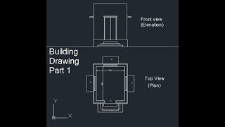
To draw the line diagram for Single storey building.
Detailed Explanation
This exercise focuses on creating a line diagram for a single-storey building. A line diagram is a simple representation that helps visualize the layout of a building, showing the basic structure and components without detailing materials or finishes. The aim is to understand the proportions and basic arrangement of spaces within the building.
Examples & Analogies
Think of the line diagram like an outline map of your favorite park. It shows the main paths and the location of the playground, but it doesn't show every flower or bench in detail. Similarly, the line diagram gives a clear view of how a single-storey building is structured.
Understanding Line Diagrams
Chapter 2 of 3
🔒 Unlock Audio Chapter
Sign up and enroll to access the full audio experience
Chapter Content
A line diagram is an essential tool for planners and architects.
Detailed Explanation
Line diagrams serve as a foundational step in the architectural design process. They are often used to convey the basic layout of rooms, walls, doors, and windows. By using simple lines to represent different structural elements, planners can easily adjust designs based on client needs or regulatory requirements.
Examples & Analogies
Imagine when you're planning a family gathering at home. You might sketch out where the tables will go, where the food will be served, and how people will move around. This sketch is similar to a line diagram, where you identify key areas in your space without necessarily detailing every single decoration.
Steps to Create a Line Diagram for a Single Storey Building
Chapter 3 of 3
🔒 Unlock Audio Chapter
Sign up and enroll to access the full audio experience
Chapter Content
Step-by-step instructions for drawing a line diagram.
Detailed Explanation
When creating a line diagram for a single-storey building, follow these steps:
1. Determine the dimensions of the building based on requirements or site constraints.
2. Sketch the outline of the building, ensuring to represent the different sections such as living areas, kitchens, and bathrooms.
3. Place internal walls to define rooms and ensure each room has a designated function.
4. Indicate the locations for doors and windows for ease of access and natural light.
5. Finally, review the layout to ensure functionality and compliance with building codes.
Examples & Analogies
Drawing your building line diagram is like planning a new layout for your classroom. First, you decide how big the classroom should be (the dimensions), then you sketch out where desks will go (the rooms), and finally, you mark where the windows and doors will be for ventilation and entry. Each step helps you create an effective learning environment.
Key Concepts
-
Importance of line diagrams: Essential for initial visualization in building design.
-
Components of line diagrams: Include walls, doors, windows, and rooms.
-
Role of CAD: Enhances precision and efficiency in drawing.
-
Best practices: Utilizing symbols, maintaining scale, and ensuring clarity.
Examples & Applications
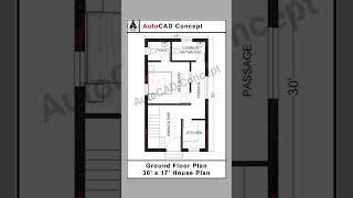
Example of a line diagram illustrating the layout of a single-storey building, including dimensions and room names.
Diagram showing the placement of doors and windows in a single-storey floor plan.
Memory Aids
Interactive tools to help you remember key concepts
Rhymes
To draw a line and make it neat, start with walls, and keep it sweet!
Stories
Imagine an architect drawing a home. Each wall is carefully placed, and every room is drawn, creating a story of where life will unfold.
Memory Tools
WADW reminds us: Walls, Areas, Doors, Windows are key in our diagrams.
Acronyms
Remember KISS
Keep It Simple
Student
whenever you draw!
Flash Cards
Glossary
- Line Diagram
A simplified drawing that shows the layout and structural elements of a building.
- CAD (ComputerAided Design)
Software used to create precise drawings and technical illustrations in engineering and architecture.
- Scale
The ratio of the dimensions in a drawing compared to the actual dimensions.
- Symbols
Graphical representations of building components, such as walls, doors, and windows in a diagram.
Reference links
Supplementary resources to enhance your learning experience.