
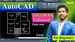
To draw the line diagram for Single storey building
Enroll to start learning
You’ve not yet enrolled in this course. Please enroll for free to listen to audio lessons, classroom podcasts and take practice test.
Interactive Audio Lesson
Listen to a student-teacher conversation explaining the topic in a relatable way.
Introduction to Line Diagrams
🔒 Unlock Audio Lesson
Sign up and enroll to listen to this audio lesson

Today we'll start by discussing what a line diagram is. Can anyone tell me why line diagrams are used in architecture?

They're used to represent buildings simply, right?
Exactly! Line diagrams simplify the representation of complex structures. They help convey essential information quickly. A good way to remember this is the phrase 'Less is more.'

What elements do we typically include in a line diagram?
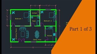
Great question! We include dimensions, walls, doors, and windows. Remember the acronym **D-W-D-W**: Dimensions, Walls, Doors, Windows. This will help you recall the key components.
Understanding Dimensions
🔒 Unlock Audio Lesson
Sign up and enroll to listen to this audio lesson

Now, let's delve into dimensions. Why do dimensions matter so much in a line diagram?

They help us understand the size and space of the building elements.
Correct! Accurate dimensions ensure that everything fits as intended. Think of it like baking; if you don't measure the ingredients right, it won't turn out well!

What happens if we miss a dimension?
Missing dimensions can lead to construction errors, which can be costly. Always double-check! To help remember, think: **Measure Twice, Draw Once**.
Symbols in Line Diagrams
🔒 Unlock Audio Lesson
Sign up and enroll to listen to this audio lesson
Next, let’s learn about the symbols we use in line diagrams. What do you think a door might look like?
Maybe a rectangle with a line representing the door opening?
Exactly! Each symbol must be clear and standardized to avoid confusion. Remember the phrase: **Standardize to Harmonize**! This helps in ensuring everyone interprets the diagram uniformly.
Are there symbols for other features too?
Yes! We have symbols for windows, walls, etc. Familiarize yourself with these symbols to enhance your diagrams.
Introduction & Overview
Read summaries of the section's main ideas at different levels of detail.
Quick Overview
Standard
In this section, students learn about the principles of creating line diagrams for single-storey buildings within the broader context of computer-aided design in building planning. Key elements such as dimensions, symbols, and layout considerations are discussed to ensure accurate representations.
Detailed
Detailed Summary
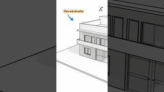
In this section, we focus on the fundamental skill essential in architecture and civil engineering: drawing line diagrams specifically for single-storey buildings. Line diagrams are simplified representations of buildings that provide a clear illustration of spatial arrangements and essential components without detailed features.
Key aspects of drawing line diagrams include understanding dimensions, which denote the lengths and widths of various building elements, and familiarizing oneself with standard symbols that represent different materials and structures (like doors, windows, walls, etc.). Additionally, the section covers considerations for layout planning for practical functionality. This essential skill not only aids in visual communication but also serves as a foundational skill before employing more complex technological tools in building design.
Youtube Videos


Key Concepts
-
Line Diagrams: Simplified representations crucial for effective communication in architectural designs.
-
Dimensions: Essential measurements that ensure proper scale and fitting in building designs.
-
Symbols: Standardized icons used for visual clarity and to represent various building elements in diagrams.
Examples & Applications
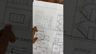
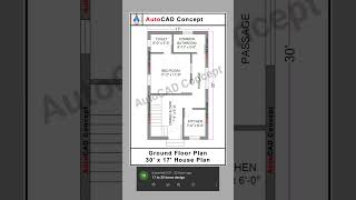
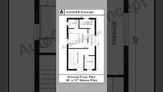
Example 1: A line diagram of a simple house showcasing basic elements such as walls, doors, and windows.
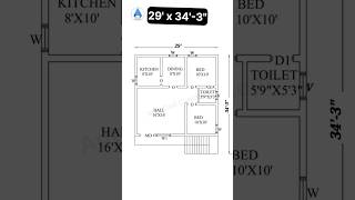
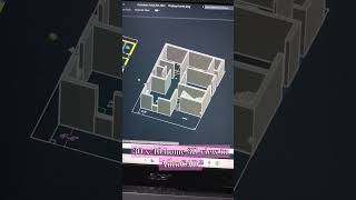
Example 2: A single-storey building’s layout used for planning interior spaces.
Memory Aids
Interactive tools to help you remember key concepts
Rhymes
For a building that's sound, lines must be found; with dimensions precise, the fit will be nice.
Stories
Imagine a builder using a map with lines to show where walls and doors should go; if he forgets the measurements, everything might not fit well, making a nice house turn into a terrible shell.
Memory Tools
Remember D-W-D-W: Dimensions, Walls, Doors, Windows for recall.
Acronyms
DWS - Dimensions, Walls, Symbols, helps to remember the key components needed in a line diagram.
Flash Cards
Glossary
- Line Diagram
A simplified drawing that represents a building’s structure and layout using lines and symbols.
- Dimension
A measurement that defines the size of an object or its components, typically represented as length and width.
- Symbols
Standard graphical representations used in diagrams to illustrate different elements like walls, doors, and windows.
Reference links
Supplementary resources to enhance your learning experience.