
Introduction to VLSI CAD Algorithms and Tools - 1
Enroll to start learning
You’ve not yet enrolled in this course. Please enroll for free to listen to audio lessons, classroom podcasts and take practice test.
Interactive Audio Lesson
Listen to a student-teacher conversation explaining the topic in a relatable way.
Introduction to VLSI CAD Algorithms
🔒 Unlock Audio Lesson
Sign up and enroll to listen to this audio lesson

Today, we're going to explore the role of CAD algorithms and tools in VLSI design. Can anyone tell me what VLSI stands for?

Yes! It stands for Very Large-Scale Integration.
Correct! VLSI refers to the integration of millions of transistors on a single chip. Now, why do you think we need CAD tools for this process?

They help automate the design process and reduce errors!
Exactly! CAD tools aid designers in modeling and optimizing circuit designs efficiently. Remember, CAD tools can be thought of as our digital toolbox in circuit design.

What types of tools do we specifically use in VLSI CAD?
Great question! Tools like synthesis, placement, routing, and simulation are used. We will dive deeper into these categories shortly. To aid your memory, you could think of the acronym SPLASH: Synthesis, Placement, Layout, Analysis, Simulation, and Hardware.

How does this relate to the design flow?
Excellent follow-up! The design flow covers stages such as specification, high-level design, logic synthesis, and verification. Let’s summarize our discussion: CAD tools automate design processes, enabling efficiency in VLSI design. Remember SPLASH for the key tools!
VLSI Design Flow
🔒 Unlock Audio Lesson
Sign up and enroll to listen to this audio lesson

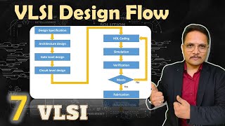
Let’s discuss the VLSI design flow. Who can list the stages in the design process?
There’s specification, high-level design, logic synthesis, placement and routing, and verification!
Correct! Each stage plays a vital role. For example, in the specification phase, we define what the circuit needs to do. Can someone describe the next stage?
High-level design is where you create a functional model of the circuit.
Exactly! After that, we move to logic synthesis, which converts our model into a gate-level representation. Any questions about these first three stages?
Yes! How do we decide where to place the components on the chip?
Great inquiry! During placement and routing, we determine physical locations while connecting components efficiently. This is key to minimizing delays and power consumption.
And verification checks if our designs meet specifications, right?
Exactly! Verification is crucial to ensure our design works as intended. To summarize, the VLSI design flow consists of five stages, each integral for the success of the design process.
Key Algorithms in VLSI CAD
🔒 Unlock Audio Lesson
Sign up and enroll to listen to this audio lesson
Now let’s move on to key algorithms used in VLSI CAD. Can anyone name one of these algorithms?
I think synthesis algorithms!
Correct! Synthesis algorithms optimize the designs. What’s another algorithm we should know about?
Placement algorithms help arrange components, right?
Exactly! Their aim is to minimize wire lengths and meet timing constraints. Can you think of a common placement algorithm?
Is it the simulated annealing algorithm?
Good example! We also have routing algorithms, which ensure proper connections while minimizing layers and maintaining integrity. Lee's algorithm is a classic example. Remember, each algorithm fulfills an essential role in handling the complexities of VLSI designs.
What about the verification algorithms?
Another excellent point! Verification algorithms validate functionality through simulation and formal verification. Let’s summarize: Key algorithms include synthesis, placement, routing, and verification, each addressing a unique challenge in the design cycle.
Introduction & Overview
Read summaries of the section's main ideas at different levels of detail.
Quick Overview
Standard
The section covers key VLSI CAD algorithms and tools necessary for automating design processes, including synthesis, placement, routing, and simulation tools. It emphasizes the design flow stages that maximize efficiency and accuracy in VLSI design.
Detailed
Introduction to VLSI CAD Algorithms and Tools
This section extensively discusses the critical algorithms and tools employed in VLSI (Very-Large-Scale Integration) design. As designers create increasingly complex integrated circuits consisting of millions of transistors, reliance on Computer-Aided Design (CAD) tools becomes paramount. CAD tools automate various design processes, facilitate design verification, and optimize design parameters (area, power, performance).
Key Topics Included:
- VLSI Design Flow: Outlines stages from specification to verification.
- Overview of CAD Tools: Describes different categories such as schematic capture, logic synthesis, placement, and simulation tools.
- Key Algorithms: Focus on synthesis, placement, routing, and verification algorithms used throughout the design process.
- Applications: Discusses custom chip design, digital and analog circuit design, and System on Chip (SoC) design.
- Challenges: Addresses complexities, performance optimization, and verification issues in VLSI CAD.
Throughout this section, readers become familiar with how these tools streamline the design process, minimize errors, and adapt to the intricacies of modern integrated circuits.
Youtube Videos


Audio Book
Dive deep into the subject with an immersive audiobook experience.
What is VLSI Design?
Chapter 1 of 4
🔒 Unlock Audio Chapter
Sign up and enroll to access the full audio experience
Chapter Content
VLSI (Very Large-Scale Integration) design involves creating complex integrated circuits by placing millions of transistors onto a single chip.
Detailed Explanation
VLSI design is a method in electronics engineering used to create integrated circuits: tiny electrical circuits built onto a semiconductor material. It allows for the integration of millions of transistors onto a single silicon chip, which can lead to powerful and compact computing devices. With this method, designers can create very intricate and functional electronics used in various applications, from computers to smartphones.
Examples & Analogies
Think of VLSI design like designing a city. Instead of buildings (transistors) being spread across a large area, everything is compacted into a city block (the chip). Just as city planners need to efficiently use space and ensure all buildings function together, engineers must carefully plan the placement and connection of millions of transistors to ensure they work smoothly together.
Importance of CAD Tools
Chapter 2 of 4
🔒 Unlock Audio Chapter
Sign up and enroll to access the full audio experience
Chapter Content
The design and manufacturing of these circuits rely heavily on specialized computer-aided design (CAD) tools and algorithms.
Detailed Explanation
Computer-Aided Design (CAD) tools are essential for modern VLSI design. They automate various processes such as modeling, analyzing, and optimizing circuit designs. Designers use these tools to simulate how the designs will behave and identify issues before the physical circuits are ever built, which saves time and reduces the possibility of errors during manufacturing.
Examples & Analogies
Imagine using architectural software to design a new building. Just as architects can visualize and modify the structure and layout of a building before it's constructed, VLSI CAD tools allow engineers to visualize and perfect their chip designs before they are manufactured, ensuring everything works as intended.
Key Role of CAD in Design Efficiency
Chapter 3 of 4
🔒 Unlock Audio Chapter
Sign up and enroll to access the full audio experience
Chapter Content
This chapter introduces the fundamental CAD algorithms and tools used in VLSI design, highlighting their role in improving efficiency and reducing errors during the design cycle.
Detailed Explanation
The introduction of CAD tools in VLSI design has revolutionized the way designers approach circuit creation. These tools not only streamline the design process but also enhance the accuracy of the designs. CAD algorithms can optimize the arrangement and operation of components within a circuit, leading to faster production times and lower costs due to fewer errors in the final designs.
Examples & Analogies
Think of a factory assembly line. CAD tools act like an efficient production line manager that ensures every part of the design process is connected and optimized. This ensures that when the circuit is built, it operates as efficiently and reliably as possible, similar to how a well-organized assembly line produces high-quality products with minimal waste.
Focus Areas of CAD Tools
Chapter 4 of 4
🔒 Unlock Audio Chapter
Sign up and enroll to access the full audio experience
Chapter Content
In this chapter, we focus on key VLSI CAD algorithms and tools that are commonly used in industry and academia:
- Design Automation: Automating the design and analysis process for integrated circuits.
- Synthesis Tools: Tools for converting high-level designs into gate-level representations.
- Layout Tools: Tools for creating physical layouts of circuits on a chip.
- Simulation Tools: Tools for analyzing the behavior and performance of the circuit before fabrication.
Detailed Explanation
The chapter outlines several specific types of CAD tools integral to VLSI design:
- Design Automation tools help automate routine tasks involved in designing and analyzing circuits, saving time and reducing manual errors.
- Synthesis Tools convert high-level design descriptions (like those written in programming languages) into detailed wiring diagrams that show how each component is physically laid out.
- Layout Tools assist in planning where each component will go on the chip, ensuring spatial efficiency.
- Simulation Tools allow designers to test their circuits in a virtual environment, making sure everything works as intended before any physical prototype is built.
Examples & Analogies
Picture a chef preparing a complex dish. Just as they might use a recipe book (synthesis tools) for step-by-step instructions, design automation helps automate meal prep tasks, while layout tools organize the kitchen (the chip) for efficient cooking. Simulation tools come in as the chef's taste test, making sure each ingredient (circuit component) blends well together before presenting the final dish (the completed chip).
Key Concepts
-
VLSI: Integration of millions of transistors into a single chip, requiring CAD tools.
-
CAD Tools: Essential software that automates design processes and minimizes errors.
-
Design Flow: The structured stages from specification to verification in VLSI design.
-
Algorithms: Key computational procedures for synthesis, placement, routing, and verification.
Examples & Applications
An example of a synthesis tool is Xilinx Vivado, which helps convert high-level description to gate-level representation.
In placement algorithms, simulated annealing is often employed to optimize component placement on the chip.
Memory Aids
Interactive tools to help you remember key concepts
Rhymes
VLSI for a chip that's so slick, millions of transistors fit quite quick.
Stories
Once there was a designer named V, who wished to place all circuits with glee. With the help of CAD tools by his side, complex designs turned into a fun ride!
Memory Tools
To remember VLSI tools: SPLASH – Synthesis, Placement, Layout, Analysis, Simulation, and Hardware.
Acronyms
CAD – Creative Assistance for Designers, helping automate the circuit design!
Flash Cards
Glossary
- VLSI
Very Large-Scale Integration, a technology that integrates millions of transistors on a single chip.
- CAD
Computer-Aided Design, tools used to assist in the design process of integrated circuits.
- Synthesis Tools
Tools that convert high-level designs into gate-level representations.
- Placement Algorithms
Algorithms that determine the physical locations of components in layout design.
- Routing Algorithms
Algorithms used to establish connections between components in circuit design.
- Verification
The process of ensuring that the design meets the required specifications.
Reference links
Supplementary resources to enhance your learning experience.