
Overview of CAD Tools for VLSI Design
Enroll to start learning
You’ve not yet enrolled in this course. Please enroll for free to listen to audio lessons, classroom podcasts and take practice test.
Interactive Audio Lesson
Listen to a student-teacher conversation explaining the topic in a relatable way.
Schematic Capture Tools
🔒 Unlock Audio Lesson
Sign up and enroll to listen to this audio lesson

Let's talk about schematic capture tools first. These tools help us create a visual representation of a circuit's logical design. Can anyone tell me what a schematic diagram typically includes?

It includes components and their connections.
Exactly! These diagrams show how the components interact logically without focusing on the physical layout yet. Remember the acronym **SC**—Schematic Capture—to keep this in mind!

Why are they so important?
Great question! They are crucial because they provide a blueprint for the circuit, helping prevent errors early in the design process.
Logic Synthesis Tools
🔒 Unlock Audio Lesson
Sign up and enroll to listen to this audio lesson

Next, let's discuss logic synthesis tools. These tools convert a high-level design, often expressed in RTL code, into a lower-level gate-level design. Does anyone know why this translation is essential?

It helps optimize the circuit for size and performance.
Exactly! **LOS**—Logic Optimization Synthesis—helps reduce the overall area and power consumption of the circuit while maintaining performance. Can anyone think of a scenario when optimization is particularly important?

In portable devices, where battery life is crucial!
Placement and Routing Tools
🔒 Unlock Audio Lesson
Sign up and enroll to listen to this audio lesson
Now we have placement and routing tools. These are responsible for determining where the components go on the chip. Why is this important?
If the components are not correctly positioned, it could affect the circuit's performance.
Right! They ensure that everything fits together while minimizing wire lengths and interference. I like to remember this with the acronym **PR**—Placement and Routing.
Do these tools also consider manufacturing constraints?
Yes, indeed! They must adhere to specific constraints to ensure that the design can be manufactured effectively.
Simulation Tools
🔒 Unlock Audio Lesson
Sign up and enroll to listen to this audio lesson
Finally, let’s explore simulation tools. These tools allow us to test the behavior of our circuit under different conditions. Why do you think this is critical?
It helps us catch errors before the hardware is built!
Exactly! It's all about preventing costly mistakes. Remember the saying, 'Test before you invest!' This ensures the design meets all functional requirements and works as expected.
So essentially, if we don’t simulate, we risk failing after fabrication?
Absolutely! The simulation phase is a crucial checkpoint in the VLSI design flow.
Introduction & Overview
Read summaries of the section's main ideas at different levels of detail.
Quick Overview
Standard
In this section, several essential categories of CAD tools used in VLSI design are discussed, including schematic capture, logic synthesis, placement and routing, and simulation tools. Each tool category plays a vital role in modeling, analyzing, and optimizing integrated circuits, contributing to more efficient design processes.
Detailed
Overview of CAD Tools for VLSI Design
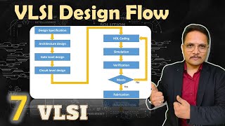
The field of VLSI (Very Large-Scale Integration) design is heavily reliant on computer-aided design (CAD) tools. This section focuses on four major categories of CAD tools that facilitate the process of designing integrated circuits:
- Schematic Capture Tools: These tools allow designers to create a logical representation of the circuit through schematics, showing components and their interconnections clearly.
- Logic Synthesis Tools: These tools are crucial for translating high-level designs, often described in Register Transfer Level (RTL) code, into optimized gate-level representations. They focus on improving the circuit’s size, power consumption, and performance.
- Placement and Routing Tools: These tools assist in physically arranging components on an integrated chip and establishing connections while respecting various manufacturing constraints. It ensures that the chip layout is efficient and functional.
- Simulation Tools: Finally, simulation tools test the circuit's behavior under various conditions to verify that it meets functional requirements before actual fabrication.
Each of these tool categories plays a significant role in the design process, helping to reduce errors and enhance the efficiency of VLSI design, emphasizing the importance of automation in the engineering of integrated circuits.
Youtube Videos


Audio Book
Dive deep into the subject with an immersive audiobook experience.
Schematic Capture Tools
Chapter 1 of 4
🔒 Unlock Audio Chapter
Sign up and enroll to access the full audio experience
Chapter Content
● Schematic Capture Tools: These tools help create the logical design of the circuit by representing components and their connections as schematics.
Detailed Explanation
Schematic Capture Tools are essential software used in VLSI design to create a visual representation of the circuit and its components. These tools allow designers to draw circuits using symbols that represent various electronic components, such as resistors, capacitors, and transistors. The connections between these components are also shown in the schematic. This representation acts as the blueprint for the circuit and is crucial for understanding how different components interact.
Examples & Analogies
Think of schematic capture as drafting a map for a new city. Just as a map outlines streets, buildings, and parks to show how the city is organized and connected, schematic capture tools outline electronic components and their wiring to represent an electronic circuit's function and layout.
Logic Synthesis Tools
Chapter 2 of 4
🔒 Unlock Audio Chapter
Sign up and enroll to access the full audio experience
Chapter Content
● Logic Synthesis Tools: These tools automatically translate a high-level design (e.g., RTL code) into a lower-level gate-level design, optimizing the circuit in terms of size, power, and performance.
Detailed Explanation
Logic Synthesis Tools are used to convert high-level descriptions of circuits, such as Register Transfer Level (RTL) code, into a gate-level representation that can be implemented physically on a chip. This process involves optimizing the design to reduce the size of the circuit, lower its power consumption, and improve performance. The tool automatically handles complex tasks such as minimizing the number of gates used and improving the signal timing in the circuit.
Examples & Analogies
Imagine turning a complex recipe into a simplified plan for cooking. Logic synthesis takes a detailed RTL recipe and transforms it into a clear step-by-step cooking plan—deciding which ingredients (gates) to use to make the dish (circuit) as efficiently as possible while ensuring it tastes great (meets performance requirements).
Placement and Routing Tools
Chapter 3 of 4
🔒 Unlock Audio Chapter
Sign up and enroll to access the full audio experience
Chapter Content
● Placement and Routing Tools: These tools help in the physical layout of the circuit, ensuring that components are correctly placed and connected on the chip while adhering to manufacturing constraints.
Detailed Explanation
Placement and Routing Tools are used in the later stages of VLSI design to determine the physical location of components on the silicon chip and to establish connections between these components. The placement stage focuses on arranging the components efficiently to minimize the distance between connected elements, which helps reduce delays and power consumption. The routing stage then connects these components using metal layers while adhering to specific manufacturing constraints, such as avoiding short circuits and ensuring signal integrity.
Examples & Analogies
Think of placement and routing as organizing a large event, like a wedding. First, you must decide where to place tables and chairs (placement) to ensure everything fits and guests can move around comfortably. Once the layout is ready, you work on ensuring that there are clear paths (routing) between the food station, dance floor, and restrooms—making sure everything is accessible and works smoothly together.
Simulation Tools
Chapter 4 of 4
🔒 Unlock Audio Chapter
Sign up and enroll to access the full audio experience
Chapter Content
● Simulation Tools: Used to test the behavior of the circuit and verify that it meets the functional requirements. They simulate the circuit's performance under various conditions to ensure it will work as expected in real-world applications.
Detailed Explanation
Simulation Tools are vital for testing how a VLSI circuit behaves before it is physically fabricated. These tools allow designers to input different scenarios and conditions, predicting how the circuit will operate under varying loads and input signals. Running simulations helps identify potential issues, such as timing errors and power problems, ensuring the design works as intended before committing to manufacturing.
Examples & Analogies
Consider simulation tools like a flight simulator used by pilots. Before flying a real airplane, pilots use simulators to practice handling different flight conditions, including turbulence and emergencies. Similarly, simulation tools help engineers test their circuits under diverse conditions, reducing the risk of failure once the circuit is built.
Key Concepts
-
Schematic Capture: The process of creating a visual representation of circuit designs.
-
Logic Synthesis: A method of optimizing high-level designs into gate-level circuits.
-
Placement and Routing: The arrangement of components on a chip and connecting them appropriately.
-
Simulation: Testing circuit behavior to ensure functionality prior to fabrication.
Examples & Applications
An example of a schematic capture tool is Cadence OrCAD, which allows designers to create circuit schematics easily.
Synopsys Design Compiler is a common logic synthesis tool used in the industry for creating optimized gate-level representations.
Memory Aids
Interactive tools to help you remember key concepts
Rhymes
Capture the schematic, keep it strategic; Synthesize your logic, make it magic!
Stories
Imagine building a Lego castle. First, you sketch it out (schematic capture), then decide which bricks build the structure (logic synthesis), make sure all pieces fit (placement and routing), and finally test its strength before showing it off (simulation).
Memory Tools
SLOPS: Schematic Capture, Logic Synthesis, Optimize with Placement and Routing, Simulate behavior.
Acronyms
C.A.P.S.
Capture (schematic)
Adapt (synthesis)
Place (routing)
Simulate (behavior).
Flash Cards
Glossary
- Schematic Capture Tools
Software tools used to create schematic representations of electronic circuits, illustrating components and their connections.
- Logic Synthesis Tools
Tools that automatically convert high-level design descriptions into optimized gate-level representations suitable for manufacturing.
- Placement and Routing Tools
Tools that facilitate the physical arrangement of components and their interconnections on integrated circuits.
- Simulation Tools
Tools used to test and analyze the behavior of circuits under different operating conditions before production.
Reference links
Supplementary resources to enhance your learning experience.