
Analog CMOS Circuit Design - Part 1: Design Principles of Operational Amplifiers in CMOS
Enroll to start learning
You’ve not yet enrolled in this course. Please enroll for free to listen to audio lessons, classroom podcasts and take practice test.
Interactive Audio Lesson
Listen to a student-teacher conversation explaining the topic in a relatable way.
Introduction to CMOS Operational Amplifiers
🔒 Unlock Audio Lesson
Sign up and enroll to listen to this audio lesson

Today we'll discuss CMOS operational amplifiers, or op-amps. An op-amp is a crucial part of many analog circuits. Can anyone tell me what applications they think op-amps might be used for?

They’re used in filtering and amplifying signals, right?
Exactly! They play a vital role in signal conditioning and amplification. Remember, op-amps are attributes of compact, high-performance designs! How about their fundamental goals? What do we aim for with an op-amp?

High gain and low distortion?
Yes! We also want low offset voltages and high input impedance. These goals will help ensure optimal performance in various applications.
Basic Components of Op-Amps
🔒 Unlock Audio Lesson
Sign up and enroll to listen to this audio lesson

Now, let's discuss the basic components of CMOS op-amps, such as NMOS and PMOS transistors. Can anyone describe the role of differential pairs?

They help amplify the voltage difference between the inputs.
Exactly, and to support this, we also use current mirrors as active loads to ensure we have stable operation. Remember, current mirrors help in maintaining high open-loop gain! How is the open-loop gain defined?

It's the output voltage divided by the difference between the input voltages, right?
You got it! This ratio is crucial for understanding the amplifier's performance.
Performance Metrics
🔒 Unlock Audio Lesson
Sign up and enroll to listen to this audio lesson
Performance metrics are essential for evaluating op-amps. Who can explain the Common-Mode Rejection Ratio, or CMRR?
It measures how well an op-amp rejects inputs that are common to both inputs!
Correct! A higher CMRR means better performance in rejecting noise. Now, what about total harmonic distortion or THD?
It indicates how much distortion the op-amp adds to the signal.
Very well explained! Low THD is particularly important for applications requiring high fidelity, like audio signals.
Design Methodology
🔒 Unlock Audio Lesson
Sign up and enroll to listen to this audio lesson
Let's move on to design methodologies. Can anyone explain the difference between the top-down and bottom-up approaches in op-amp design?
The top-down approach specifies requirements first and designs each stage, while the bottom-up approach builds the stages with selected components.
Exactly! Also, simulation is crucial to optimize the performance of the design. What tools can we use for simulation?
Tools like SPICE or LTspice?
Right! These tools help us validate designs under various conditions and ensure they meet specifications.
Introduction & Overview
Read summaries of the section's main ideas at different levels of detail.
Quick Overview
Standard
The section highlights the significance of CMOS operational amplifiers in analog circuit design, detailing the crucial components such as differential pairs, current mirrors, and active loads. It covers key performance metrics including open-loop gain, common-mode rejection ratio, and presents various design methodologies to achieve efficient, high-performance op-amps.
Detailed
Detailed Summary of CMOS Operational Amplifier Principles
The chapter discusses the design principles for CMOS operational amplifiers (op-amps), which are vital components in modern analog electronics used in applications like signal conditioning and filtering. The goals of op-amp design in CMOS technology include achieving high gain, low offset, minimal distortion, and high input impedance while maintaining low power consumption.
Key Components of CMOS Op-Amps
- CMOS Transistor Basics: The op-amps consist of NMOS and PMOS transistors configured mainly in differential pairs to amplify input voltage differences, supported by current mirrors for biasing and active loads.
- Open-Loop Gain: The open-loop gain (
A_{OL}) defines the amplification factor without feedback, being crucial for op-amp performance. A high open-loop gain is sought after to ensure effective amplification. - Common-Mode Rejection Ratio (CMRR): CMRR measures the op-amp's ability to ignore noise signals common to both inputs, promoting the amplification of only the differential signal.
- Input and Output Impedance: High input impedance prevents loading issues, while low output impedance facilitates effective load driving.
Performance Metrics
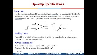
The section also elaborates on performance metrics like slew rate (the speed of output voltage changes), unity gain bandwidth (the frequency at which gain equals one), and total harmonic distortion (THD).
Design Methodologies
Two primary design methodologies are presented: a top-down approach that starts from performance specifications and a bottom-up approach that involves designing individual stages. Simulation tools are emphasized for validating designs under various conditions, leading to opportunity for optimization.
In summary, understanding these principles and metrics is crucial for designing efficient CMOS op-amps that meet the requirements of modern electronic systems.
Youtube Videos
Audio Book
Dive deep into the subject with an immersive audiobook experience.
Introduction to CMOS Operational Amplifiers (Op-Amps)
Chapter 1 of 6
🔒 Unlock Audio Chapter
Sign up and enroll to access the full audio experience
Chapter Content
An Operational Amplifier (Op-Amp) is a key analog component used in various applications such as signal conditioning, filtering, amplification, and feedback systems. CMOS technology allows the design of compact, high-performance op-amps that are integral to many modern electronic devices, from audio amplifiers to analog-to-digital converters (ADC). In CMOS analog circuit design, the main goal is to design an op-amp that offers high gain, low offset, low distortion, and high input impedance while minimizing power consumption.
Detailed Explanation
This chunk introduces operational amplifiers, which are essential components in many electronic devices. Op-Amps enhance signals, filter noise, and can even generate feedback to stabilize systems. The use of CMOS technology in Op-Amps allows for their compactness and performance efficiency, making them suitable for devices like audio amplifiers and converters. The primary objectives in designing a CMOS Op-Amp are achieving significant amplification (high gain), ensuring minimal error (low offset), reducing distortion in signals, and maximizing the input impedance while keeping power consumption low.
Examples & Analogies
Imagine an Op-Amp as a sound mixer at a concert. Just like a mixer amplifies sound signals, adjusts volume, and minimizes noise, an Op-Amp augments electronic signals in circuits. The use of CMOS technology allows this mixer to be small and efficient, which is crucial for modern devices that fit easily into our pockets.
Basic Principles of CMOS Operational Amplifiers
Chapter 2 of 6
🔒 Unlock Audio Chapter
Sign up and enroll to access the full audio experience
Chapter Content
In CMOS operational amplifiers, NMOS and PMOS transistors are used to form the basic building blocks of the amplifier. These include: ● Differential Pairs: Used to amplify the difference between the input voltages. ● Current Mirrors: Used to set and mirror currents in various parts of the circuit. ● Active Load: Typically a current mirror or PMOS transistor that provides the necessary load for the differential pair. The performance of an op-amp is defined by how these components are configured and interact to achieve a high gain with low offset voltage, low power consumption, and high stability.
Detailed Explanation
This section discusses the foundational components of CMOS Op-Amps, specifically NMOS and PMOS transistors. These transistors come together to form critical structures like differential pairs, which focus on amplifying the difference between two input voltages, current mirrors, which keep a consistent current flow, and active loads that help maintain the circuit's performance. Essentially, how these elements are arranged determines the Op-Amp’s efficacy in providing high amplification with minimal errors.
Examples & Analogies
Think of the differential pair as two competitors in a race. They try to see who crosses the finish line (the amplified difference) first. Meanwhile, the current mirror acts like a coach who ensures both are fueled adequately, and the active load is like a cheering crowd that helps motivate the runners to perform at their best.
Op-Amp Open-Loop Gain
Chapter 3 of 6
🔒 Unlock Audio Chapter
Sign up and enroll to access the full audio experience
Chapter Content
The open-loop gain (AOLA_{OL}) of an op-amp is the ratio of the output voltage to the difference in the input voltages without any feedback applied. It is an important performance parameter and is ideally as large as possible. The open-loop gain in a CMOS op-amp can be defined by: AOL=voutvin+−vin−A_{OL} = \frac{v_{out}}{v_{in+} - v_{in-}} Where: ● vin+v_{in+} is the non-inverting input, ● vin−v_{in-} is the inverting input, ● voutv_{out} is the output voltage. A high AOLA_{OL} is desired, and it is typically achieved using a differential pair of transistors with a high-impedance load.
Detailed Explanation
Open-loop gain represents the raw amplification capability of the Op-Amp without feedback affecting it. It's calculated as the output voltage divided by the difference in input voltages. The goal is for this gain to be as high as possible to ensure efficient amplification. Using a differential pair allows designers to maximize this gain because it can effectively amplify voltage discrepancies, creating a stronger output signal.
Examples & Analogies
Think of the open-loop gain as the volume of a speaker before adjusting it with a remote. The speaker can produce a loud sound (high gain) based on how much difference there is in sound signals (input voltage). The more pronounced the difference, the louder the sound (higher output).
Common-Mode Rejection Ratio (CMRR)
Chapter 4 of 6
🔒 Unlock Audio Chapter
Sign up and enroll to access the full audio experience
Chapter Content
The CMRR is the ability of an op-amp to reject common-mode signals, i.e., signals that are present on both inputs simultaneously. A high CMRR ensures that the op-amp amplifies only the difference between the inputs while rejecting noise or interference that is common to both inputs. The CMRR is given by: CMRR=AOLACM\text{CMRR} = \frac{A_{OL}}{A_{CM}} Where: ● AOLA_{OL} is the open-loop differential gain, ● ACMA_{CM} is the open-loop common-mode gain.
Detailed Explanation
CMRR quantifies how well an Op-Amp can ignore signals that affect both inputs equally. A high CMRR means the Op-Amp focuses on what really matters—the difference between inputs—making it ideal in noisy environments where external signals can interfere. It's expressed as the ratio of the differential gain to the common-mode gain, helping engineers understand how well their designs can filter out noise.
Examples & Analogies
Imagine trying to listen to a conversation in a crowded café. A high CMRR is like having noise-canceling headphones that let you hear your friend clearly while blocking out background chatter. You’re amplifying only the important signal (the conversation) and ignoring the noise around you.
Input and Output Impedance
Chapter 5 of 6
🔒 Unlock Audio Chapter
Sign up and enroll to access the full audio experience
Chapter Content
● Input Impedance: The input impedance of an op-amp is defined as the resistance seen by the input signal. High input impedance is desired to avoid loading the source circuit and ensure maximum signal transfer. ● Output Impedance: The output impedance defines how much the output voltage will change in response to changes in output current. A low output impedance is desirable to drive loads effectively without significant voltage drop. In a well-designed CMOS op-amp, the input impedance is typically very high, and the output impedance is low, especially when operating in a closed-loop configuration.
Detailed Explanation
Input and output impedance are crucial for an Op-Amp's functionality. High input impedance means the Op-Amp draws minimal current, preventing interference with the source it's measuring. Low output impedance indicates that the Op-Amp can drive loads effectively, maintaining a stable voltage despite changes in output current. Good designs seek to maximize input impedance while minimizing output impedance, especially in closed-loop circuits where feedback is used.
Examples & Analogies
Think of input impedance as a sponge soaking up water. If the sponge (Op-Amp) has a high resistance (input impedance), it won’t soak too much water from the bucket (input source). Conversely, output impedance is like a faucet; if it’s low, the faucet can deliver steady water flow (output voltage) even when someone adjusts the tap (changes in load).
Key Components in CMOS Operational Amplifier Design
Chapter 6 of 6
🔒 Unlock Audio Chapter
Sign up and enroll to access the full audio experience
Chapter Content
The differential amplifier forms the core of most op-amps. It amplifies the difference between the two input voltages and is typically implemented using NMOS transistors in a differential pair configuration.
Detailed Explanation
The differential amplifier is fundamental to the operation of an Op-Amp. It focuses on amplifying the difference rather than the absolute values of the inputs, which is critical for precise signal processing. NMOS transistors are frequently used in this configuration to leverage their efficient performance characteristics. The differential pair design combines multiple transistors to ensure that they effectively manage current flow based on input voltage differences.
Examples & Analogies
In a survey about favorite flavors, the differential amplifier is like a counting system that determines preferences based on the difference between responses rather than treating all answers equally. If one flavor is chosen significantly more than another, the system amplifies that preference difference for clearer insights.
Key Concepts
-
Operational Amplifier (Op-Amp): A key component in analog electronics for signal amplification.
-
Differential Pair: A configuration used in op-amps for amplifying the voltage difference between two inputs.
-
Open-Loop Gain: The amplification factor without feedback, crucial for performance evaluation.
-
Common-Mode Rejection Ratio (CMRR): Indicates how well an op-amp rejects common signals on both inputs.
-
Slew Rate: A measure of the speed at which an op-amp output can change.
-
Total Harmonic Distortion (THD): A measure of the distortion in the output signal of the op-amp.
Examples & Applications
A common application of op-amps includes audio amplification, where high fidelity is crucial, necessitating low THD.
In sensor applications, op-amps are used to amplify small signals, allowing for accurate readings in systems like temperature sensors.
Memory Aids
Interactive tools to help you remember key concepts
Rhymes
Op-amps amplify and filter, their roles in circuits they’ll never wither.
Stories
Imagine a postman (the op-amp) delivering letters (input signals) to two boxes (inputs); he only pays attention to the differences in letter contents—this shows how op-amps work in amplifying differences.
Memory Tools
Remember CMRR = Can't Measure Rivalry Rejection— for common mode rejection ratio.
Acronyms
Acronym for op-amp design principles 'G-LOWS'
Gain
Low distortion
Offset
Wide bandwidth
Stability.
Flash Cards
Glossary
- Operational Amplifier (OpAmp)
An electronic component that amplifies the difference between two input voltages.
- CMOS
Complementary Metal-Oxide-Semiconductor; a technology used for constructing integrated circuits.
- OpenLoop Gain (AOL)
The gain of an op-amp without any feedback applied.
- CommonMode Rejection Ratio (CMRR)
The ability of an op-amp to reject common-mode signals that appear on both inputs simultaneously.
- Total Harmonic Distortion (THD)
A measure of the distortion introduced by the amplifier, expressed as a ratio of harmonic content to the original signal.
- Slew Rate
The maximum rate at which the output voltage can change in response to changing input signal conditions.
- Unity Gain Bandwidth (GBW)
The frequency at which the op-amp's gain drops to unity (1).
- Differential Pair
A configuration of two transistors that amplifies the difference between two input signals.
- Current Mirror
A circuit that replicates a current through one active device to another, used as a biasing element.
- Active Load
A load element that dynamically adjusts to help maintain consistent flow in the operational circuit.
Reference links
Supplementary resources to enhance your learning experience.