
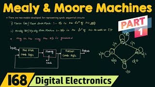
State Diagram Example (Moore Machine)
Interactive Audio Lesson
Listen to a student-teacher conversation explaining the topic in a relatable way.
Introduction to Moore Machines
🔒 Unlock Audio Lesson
Sign up and enroll to listen to this audio lesson

Today, we're going to explore Moore machines, specifically using the traffic light controller as an example. Can anyone tell me what a Moore machine is?

Is it a type of state machine where the outputs depend only on the current state?
Exactly! In Moore machines, the outputs are based solely on the state. Now, let's think about our traffic light controller. What states do you think a traffic light can have?

Red, green, yellow, and maybe a red plus yellow?
Great job! Those are the states: S0 as Red, S1 as Red + Yellow, S2 as Green, and S3 as Yellow. Each light corresponds to a specific state.

How do the transitions happen between these states?
Good question! Transitions occur based on timeouts. Each state lasts for a predefined clock cycle before moving to the next state.
To summarize, in a Moore machine, outputs are determined by current states, which are fixed and transition over time.
State Transitions in Traffic Lights
🔒 Unlock Audio Lesson
Sign up and enroll to listen to this audio lesson

Now that we know the states, let’s discuss transitions between them. Can anyone show me how these transitions occur in a traffic light?

The light changes from red to red + yellow, then to green, then to yellow, and back to red?
Correct! We start from Red (S0), switch to Red + Yellow (S1), then to Green (S2), and finally to Yellow (S3). Each state waits based on a clock count.
So, it’s like each light has a timer controlling how long it stays on.
Yes! The fixed clock count ensures that the light state lasts for a determined period. This structure helps in managing traffic efficiently.
In summary, the transitions allow the light controller to function systematically, preventing accidents and ensuring traffic flow.
Importance of Fixed States
🔒 Unlock Audio Lesson
Sign up and enroll to listen to this audio lesson
Let’s talk about why fixed states are critical in our traffic light control system. Why do you think it's essential to have defined states?
It makes the system predictable, right? Drivers know what to expect.
Exactly! Predictability is key. What happens if states aren’t well defined?
It could cause confusion for drivers and lead to accidents.
Right! Fixed states ensure that every participant in traffic knows what to expect, which enhances safety.
To summarize, fixed states provide structure and reliability in traffic management systems.
Introduction & Overview
Read summaries of the section's main ideas at different levels of detail.
Quick Overview
Standard
In this section, the concept of state diagrams as applied to Moore machines is explored, specifically illustrating the transitions and fixed states of a traffic light controller. Each state corresponds to a specific light, with transitions dependent on timed intervals.
Detailed
State Diagram Example (Moore Machine)
In this section, we delve into state diagrams, with a focus on a practical application of a Moore machine. The example of a Traffic Light Controller is used to explain the concept comprehensively. A Moore machine is characterized by its outputs solely depending on the current state, with fixed states playing crucial roles in sequential circuits.
Key Concepts Covered:
- States: The traffic light controller comprises four primary states:
- S0: Red
- S1: Red + Yellow
- S2: Green
- S3: Yellow
Each of these states represents a specific function of the traffic light system. - State Duration: Each state is maintained for a fixed clock count, enabling a predictable timing structure.
- Transitions: The transitions between these states occur based on timeouts rather than immediate inputs, distinguishing it from Mealy models where outputs can change on inputs.
This analysis of the Moore machine with a traffic light example helps illustrate the practical aspects of state machines in embedded systems, emphasizing how temporal sequences govern state changes.
Youtube Videos


Audio Book
Dive deep into the subject with an immersive audiobook experience.
Overview of the Traffic Light Controller States
Chapter 1 of 2
🔒 Unlock Audio Chapter
Sign up and enroll to access the full audio experience
Chapter Content
States:
● S0: Red
● S1: Red + Yellow
● S2: Green
● S3: Yellow
Detailed Explanation
In this section, we are introduced to the concept of states in a traffic light controller using a Moore machine model. Here, the traffic light can exist in one of four states:
1. S0: Red - The traffic light is red, stopping all traffic.
2. S1: Red + Yellow - The light is red and yellow, indicating that the light will soon change to green.
3. S2: Green - This state allows traffic to proceed.
4. S3: Yellow - Indicates that the light is about to turn red. Each state represents a fixed condition that the traffic light can be in at any given time.
Examples & Analogies
Imagine a traffic light as a character in a story, where the character can be in different moods represented by different colors. When the character is in a red mood, they are telling everyone to stop. When they switch to yellow, they're warning that they will soon change their mood. When they're green, they're ready for action, and when they are yellow again, they're about to slow down.
Timing and Transitions
Chapter 2 of 2
🔒 Unlock Audio Chapter
Sign up and enroll to access the full audio experience
Chapter Content
Each state lasts for a fixed clock count. Transitions occur on timeouts.
Detailed Explanation
In a Moore machine, each state has a specific duration during which it remains active. In the case of the traffic light controller, each state lasts for a fixed number of clock cycles. After a designated amount of time, the controller transitions from one state to another based on timeouts, ensuring that the lights change at regular intervals. For instance, the red light may stay on for a certain number of seconds before switching to the red + yellow light.
Examples & Analogies
Think of a timer in a game that counts down seconds for each level. Just like the timer, the traffic light controller has a countdown timer for each state, determining how long it stays in each color before transitioning to the next state.
Key Concepts
-
States: The traffic light controller comprises four primary states:
-
S0: Red
-
S1: Red + Yellow
-
S2: Green
-
S3: Yellow
-
Each of these states represents a specific function of the traffic light system.
-
State Duration: Each state is maintained for a fixed clock count, enabling a predictable timing structure.
-
Transitions: The transitions between these states occur based on timeouts rather than immediate inputs, distinguishing it from Mealy models where outputs can change on inputs.
-
This analysis of the Moore machine with a traffic light example helps illustrate the practical aspects of state machines in embedded systems, emphasizing how temporal sequences govern state changes.
Examples & Applications
In a traffic light controller, the states include Red, Red + Yellow, Green, and Yellow, transitioning based on time intervals.
Similarly, a vending machine can also be viewed as a Moore machine where the current selection state dictates the machine's outputs.
Memory Aids
Interactive tools to help you remember key concepts
Rhymes
For a traffic light always stay bright, Red then yellow, green takes flight!
Stories
Imagine a traffic light as a wise old man, with a clock that tells him when to change his colors...
Memory Tools
R-G-Y-R means Red-Green-Yellow-Red for the traffic flow sequence for a quick recall.
Acronyms
TLC for Traffic Lights in a Controller
Timed
Light
Controlled.
Flash Cards
Glossary
- Moore Machine
A type of finite state machine where outputs depend only on the current state.
- State
A specific condition or situation that a system can be in at any given time.
- Transition
The process of moving from one state to another based on certain criteria or conditions.
- Traffic Light Controller
A system designed to control vehicle and pedestrian traffic at intersections using colored lights.
- Clock Count
A predetermined period for which a state remains active in a sequential circuit.
Reference links
Supplementary resources to enhance your learning experience.