
Steps to Design a Sequential Circuit
Interactive Audio Lesson
Listen to a student-teacher conversation explaining the topic in a relatable way.
Understanding the Problem
🔒 Unlock Audio Lesson
Sign up and enroll to listen to this audio lesson

The first step in designing a sequential circuit is understanding the problem. Can anyone tell me why this is crucial?

I guess it's important because if we don't know what the circuit needs to do, we can't design it properly!
Exactly! Without a clear objective, all subsequent steps can lead us astray. What kind of details do we need to know about the problem?

We need to know the inputs and what outputs we want from the circuit.
Right! That's called defining the scope of the circuit. Now let's remember this with the acronym 'SCOPE'—Specify Current Objectives and Product Expectations. This will help us always remember to clarify the problem first.
Identifying States
🔒 Unlock Audio Lesson
Sign up and enroll to listen to this audio lesson

After understanding the problem, what's next?

We need to identify the states!
Correct! Why is identifying states significant?
Because each state reflects our outputs depending on past inputs.
Correct again! Think of states as snapshots during the circuit's operation. Can anyone give an example of a state?

For a traffic light, states could be 'Red', 'Yellow', and 'Green'.
Exactly! Use the mnemonic 'SSS'—States Show Status. This will help us remember the purpose of identifying states.
Drawing the State Diagram
🔒 Unlock Audio Lesson
Sign up and enroll to listen to this audio lesson
What do we do after identifying the states?
We draw a state diagram!
Yes! A state diagram visualizes how our circuit transitions from one state to another based on inputs. What components does it include?
It includes states and transitions, which show how the circuit moves between them.
Perfect! Remember the phrase 'DID IMPRINT'—Draw Important Diagrams for Input Mapping and Transition. This will help you when creating these diagrams.
Building the State Table
🔒 Unlock Audio Lesson
Sign up and enroll to listen to this audio lesson
After drawing a state diagram, what’s the next step?
We build a state table!
Exactly! The state table organizes our states, next states, and outputs in a clear format. Why is this organization critical?
It helps us easily see how states and transitions relate to each other.
Good point! Remember the term 'CLEAR'—Construct Lists to Enumerate All Relationships. This keeps us focused on the relationships in the state table!
Introduction & Overview
Read summaries of the section's main ideas at different levels of detail.
Quick Overview
Standard
The section details a systematic approach to designing sequential circuits, from comprehending the problem to developing logic diagrams. Key steps include identifying states, drawing state diagrams, building state tables, selecting flip-flop types, deriving excitation tables, and drawing logic diagrams, all aimed at creating a functional sequential circuit.
Detailed
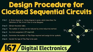
Steps to Design a Sequential Circuit
Designing sequential circuits requires a systematic approach to ensure accuracy and functionality. The steps outlined in this section are critical for students and engineers alike who want to create sequential circuits effectively.
- Understand the problem: Before diving into design, it's important to clearly define what the circuit needs to accomplish. Properly understanding the problem sets the foundation for successful design.
- Identify the states: Recognizing the various states of the circuit is crucial as each state represents an output that depends on both current inputs and past history.
- Draw the state diagram: The state diagram visually represents how the circuit transitions from one state to another based on input changes. This graphical method simplifies the design process.
- Build a state table: Constructing a state table aids in organizing the current state, possible next states, and corresponding outputs systematically. This tabular representation serves as a blueprint for further design steps.
- Choose flip-flop type (D, T, JK): Deciding on the appropriate flip-flop type is essential, as each flip-flop has unique characteristics that affect how states change during operation.
- Derive excitation table and expressions: This step involves calculating the conditions under which flip-flops change states, helping ensure the desired transition behavior is achieved in the circuit.
- Draw logic diagram: The final step is to create the logic diagram, representing the entire circuit including all flip-flops and their interconnections. This diagram acts as the physical implementation plan for constructing the circuit.
Understanding these steps empowers designers to create efficient and reliable sequential circuits, combining knowledge of digital logic with systematic design techniques.
Youtube Videos


Audio Book
Dive deep into the subject with an immersive audiobook experience.
Understanding the Problem
Chapter 1 of 7
🔒 Unlock Audio Chapter
Sign up and enroll to access the full audio experience
Chapter Content
- Understand the problem
Detailed Explanation
The first step in designing a sequential circuit is to carefully understand the problem at hand. This involves identifying what the circuit is supposed to do, including its inputs, outputs, and the desired behavior over time. It's essential to know the specific requirements and constraints that the circuit must meet.
Examples & Analogies
Imagine you're tasked with designing a smart doorbell that triggers different actions based on whether a visitor presses the button or not. You need first to understand what signals (inputs) you're working with and what responses (outputs) are needed.
Identifying States
Chapter 2 of 7
🔒 Unlock Audio Chapter
Sign up and enroll to access the full audio experience
Chapter Content
- Identify the states
Detailed Explanation
After understanding the problem, the next step is to identify the states of the system. A state represents a specific condition or situation that the circuit can be in at any given moment. Mapping out these states helps visualize how the circuit transitions from one condition to another based on input signals.
Examples & Analogies
Think of a traffic light system. The states could be 'Red', 'Green', and 'Yellow'. Each of these states indicates what the light should display, and understanding these is crucial for controlling traffic.
Drawing the State Diagram
Chapter 3 of 7
🔒 Unlock Audio Chapter
Sign up and enroll to access the full audio experience
Chapter Content
- Draw the state diagram
Detailed Explanation
Once the states are identified, you should create a state diagram. This diagram is a graphical representation of the states and how they transition based on inputs. It helps in visualizing the overall behavior of the sequential circuit and ensuring that all possible transitions are considered.
Examples & Analogies
Continuing with the traffic light analogy, the state diagram would show how the light changes from Red to Green, then to Yellow, and back to Red, with arrows indicating the transitions based on time or sensors.
Building the State Table
Chapter 4 of 7
🔒 Unlock Audio Chapter
Sign up and enroll to access the full audio experience
Chapter Content
- Build a state table (present state, next state, outputs)
Detailed Explanation
The next step involves constructing a state table. The state table lists the current (present) states and specifies what the next states will be, as well as the outputs that occur in each state. This table serves as a useful reference for understanding how the circuit behaves as it changes states.
Examples & Analogies
Using our traffic light controller, the state table would specify that when the light is in the 'Red' state, the next state is 'Green', with an output indicating that cars can proceed when the light turns green.
Choosing Flip-Flop Type
Chapter 5 of 7
🔒 Unlock Audio Chapter
Sign up and enroll to access the full audio experience
Chapter Content
- Choose flip-flop type (D, T, JK)
Detailed Explanation
The fifth step is to select the appropriate type of flip-flop for the design. Common types include D flip-flops, T flip-flops, and JK flip-flops, each serving different needs in the circuit. The choice depends on the required operation, such as how data is stored and how transitions occur.
Examples & Analogies
Consider choosing the right tool for a specific repair task. Just as you would select a hammer for nails but a screwdriver for screws, selecting the right flip-flop type is crucial for proper circuit functionality.
Deriving Excitation Table and Expressions
Chapter 6 of 7
🔒 Unlock Audio Chapter
Sign up and enroll to access the full audio experience
Chapter Content
- Derive excitation table and expressions
Detailed Explanation
In this step, you derive the excitation table and logical expressions needed to control the flip-flops. The excitation table shows the required inputs for the flip-flops based on the current and next states, which aids in determining how to manipulate the circuit effectively.
Examples & Analogies
This is similar to preparing a recipe by listing the ingredients (excitation table) and instructions (expressions) you’ll need to create a dish, ensuring that everything is in place for the final output.
Drawing the Logic Diagram
Chapter 7 of 7
🔒 Unlock Audio Chapter
Sign up and enroll to access the full audio experience
Chapter Content
- Draw logic diagram
Detailed Explanation
The final step involves creating a logic diagram that visually represents the complete circuit design. This diagram will include all the components (like flip-flops and gates) and their connections as per the derived expressions. This creates a blueprint that can be used for building the actual circuit.
Examples & Analogies
Imagine this as drawing a map before a road trip. The logic diagram is your roadmap, guiding you on how to set up the circuit components to reach your destination (the intended functioning circuit).
Key Concepts
-
Understanding the Problem: Clearly defining the circuit's purpose is essential for effective design.
-
Identifying States: Recognizing the different states that the circuit can occupy helps in the transition logic.
-
State Diagrams: Visual representations that map states and transitions, clarifying how the circuit operates.
-
State Tables: Organizational tables that list current states, next states, and their outputs, critical for logic design.
Examples & Applications
In designing a traffic light controller, the states could be Red, Yellow, and Green, each having defined transitions based on timed intervals.
For a binary counter, states would reflect the binary values from 00 to 11 with transitions occurring at each clock pulse.
Memory Aids
Interactive tools to help you remember key concepts
Rhymes
When in doubt, write it out, know the states, avoid mistakes.
Stories
Imagine a traffic light that only works when you know the order and duration of its signals. Each phase of light is a point in its journey—a state that it's essential to recognize.
Memory Tools
USE DECLARE to remember: Understand, States, and Draw - always use the steps in order!
Acronyms
SCOPE
Specify Current Objectives and Product Expectations - helps in defining the problem.
Flash Cards
Glossary
- Sequential Circuit
A circuit whose output depends on current inputs and past history, usually involving memory elements.
- State Diagram
A graphical representation of a sequential circuit that shows states and transitions based on inputs.
- FlipFlop
A basic memory element used in sequential circuits to store state information.
- State Table
A tabular format that outlines the current state, next state, and outputs of a sequential circuit.
Reference links
Supplementary resources to enhance your learning experience.