
Design of FIR Filters
Interactive Audio Lesson
Listen to a student-teacher conversation explaining the topic in a relatable way.
Choosing the Desired Frequency Response
🔒 Unlock Audio Lesson
Sign up and enroll to listen to this audio lesson

To begin designing an FIR filter, we must define the desired frequency response. This means determining what type of signal characteristics we want to keep or enhance.

What exactly do you mean by 'frequency response'?
Great question! The frequency response is how the filter alters the amplitudes and phases of different frequency components in a signal. For instance, in a low-pass filter, we want to allow low frequencies to pass while attenuating high frequencies.

So how do we know which type of filter to use?
It depends on the application's requirements. For example, if we're working with audio signals and want to reduce noise, a low-pass filter is often a good choice. Remember the acronym 'CLEAR'—Cutoff frequency, Low-pass, Enhance low frequencies, Attenuate high frequencies, Response shape.

How does one define those cutoff frequencies?
Cutoff frequencies can be derived from the signal characteristics, usually by analyzing the frequency domain representation of the input signal.
Selecting the Filter Length (N)
🔒 Unlock Audio Lesson
Sign up and enroll to listen to this audio lesson

Once we've established our desired frequency response, the next step is to choose the filter length, denoted as N.

What does that filter length actually do?
The filter length determines how many past input samples we consider for filtering. A larger N means better noise reduction but also more computation.
Is there a trade-off involved?
Absolutely! Think of it like a balance scale: too short of a filter may not reduce noise effectively, while too long can slow down processing time. Always aim for 'Optimal Length' which is your sweet spot!
So how do we find that sweet spot?
Experimentation and performance testing in real-world conditions are crucial for determining the ideal filter length.
Windowing Methods
🔒 Unlock Audio Lesson
Sign up and enroll to listen to this audio lesson
Now, let's talk about windowing methods. This crucial step often helps improve filter performance after we've defined the impulse response.
What exactly is windowing, and why is it important?
Windowing involves applying a mathematical function, called a window function, to the ideal impulse response. It helps in reducing side lobes in the frequency response, hence minimizing undesired oscillations.
Can you give an example of a windowing function?
Certainly! Common examples include the Hamming, Hanning, and Blackman windows. Each has distinct characteristics suited for different applications. Remember the mnemonic 'HAM' for Hamming, Amplitude, and Maximum!
How do we know which window to use?
It depends on the desired trade-offs in terms of main lobe width and side lobe level. Simulation tools can help analyze these factors.
Computing Filter Coefficients
🔒 Unlock Audio Lesson
Sign up and enroll to listen to this audio lesson
Finally, computing the filter coefficients brings us to the end of our design process.
How does one calculate these coefficients?
There are various methods like the frequency sampling method, the Parks-McClellan algorithm, and the window method. Each has different use cases.
Could you elaborate on the Parks-McClellan algorithm?
Of course! The Parks-McClellan algorithm is an optimal design method for filters with linear phase response and is widely used for its effectiveness.
Do we have to understand all these methods, or can we use online tools?
While online tools can help streamline the process, understanding these methods allows you to design filters that are tailored specifically to your needs.
Introduction & Overview
Read summaries of the section's main ideas at different levels of detail.
Quick Overview
Standard
Designing FIR filters requires defining the desired frequency response according to the application, choosing an appropriate filter length to balance noise reduction and computational complexity, applying different windowing methods to enhance performance, and calculating the corresponding filter coefficients through various techniques.
Detailed
Design of FIR Filters
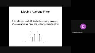
The design of Finite Impulse Response (FIR) filters, including moving average filters, is a systematic process crucial for various digital signal processing applications. FIR filters are known for their stability and linear phase response. The design process typically consists of the following key steps:
- Choosing the Desired Frequency Response: The first step is to specify the necessary frequency response characteristics. This includes deciding on the cutoff frequencies and the desired filter shape, which can be low-pass, high-pass, or other types based on the application requirements.
- Selecting the Filter Length (N): The filter length determines the number of samples that will be utilized in calculating the moving average or the filter’s output. A longer filter generally improves noise reduction capabilities but also increases computational complexity.
- Windowing Methods: FIR filter design often employs windowing techniques. This involves multiplying the ideal impulse response by a window function (such as Hamming, Hanning, or Blackman windows) to minimize side lobes in the frequency response, thereby improving overall filter performance.
- Computing Filter Coefficients: Finally, various methods are available for calculating the filter coefficients. Common approaches include the frequency sampling method, Parks-McClellan algorithm, or using the window method. Each of these has distinct principles and is suited for different design considerations.
By following these steps, designers can effectively tailor FIR filters to meet specific requirements in diverse applications like noise reduction and signal processing.
Youtube Videos

Audio Book
Dive deep into the subject with an immersive audiobook experience.
Choosing the Desired Frequency Response
Chapter 1 of 4
🔒 Unlock Audio Chapter
Sign up and enroll to access the full audio experience
Chapter Content
The desired cutoff frequency and shape of the filter's frequency response (e.g., low-pass, high-pass, band-pass) must be defined based on the application.
Detailed Explanation
When designing an FIR filter, the first step is to decide what frequencies you want to allow through and which ones to block. This is done by defining the desired frequency response of the filter. For example, if you're designing a low-pass filter, you want to let low frequencies pass through while blocking high frequencies. The specifics of how abrupt or gradual this transition is will depend on the application and the characteristics needed for the output signal.
Examples & Analogies
Think of this as designing a gate for a swimming pool where you want to block high waves while allowing calm water to flow in. Depending on how you set the gate, you can control what comes into the pool effectively.
Selecting the Filter Length
Chapter 2 of 4
🔒 Unlock Audio Chapter
Sign up and enroll to access the full audio experience
Chapter Content
The filter length determines the number of samples used to compute the moving average. A longer filter (larger N) will result in better noise reduction but will also increase the computational complexity.
Detailed Explanation
The length of the FIR filter, denoted by N, is significant in shaping how effectively the filter works. A longer filter length means that it considers more input samples when calculating the output, which can lead to better smoothing and noise reduction. However, a longer filter also requires more calculations, which can increase the time it takes for the filter to process the input signal, impacting performance in real-time applications.
Examples & Analogies
Imagine you're cleaning a window. If you use a bigger squeegee (longer filter), you can cover more area at once, making the window clean faster (better noise reduction). However, if the squeegee is too large, you might have a hard time maneuvering it properly, leading to streaks instead (increased complexity).
Windowing Methods
Chapter 3 of 4
🔒 Unlock Audio Chapter
Sign up and enroll to access the full audio experience
Chapter Content
The design of FIR filters often involves windowing techniques, where the ideal filter impulse response is multiplied by a window function (e.g., Hamming, Hanning, or Blackman window) to reduce side lobes and improve the filter's performance.
Detailed Explanation
Windowing methods are techniques used to reshape the ideal impulse response of a filter. By applying a windowing function, you can smooth the edges of the impulse response to reduce unwanted oscillations known as side lobes. This is crucial because, without this smoothing, abrupt changes can cause distortion in the frequency response of the filter, negatively affecting its performance. Different window functions can achieve different results, and the choice depends on the specific application.
Examples & Analogies
It's akin to using a soft cloth to rub a surface for cleaning. Just like how a soft cloth will avoid scratching the surface while being effective, using a windowing function helps to make the filter response smoother and more effective without creating distortion.
Computing Filter Coefficients
Chapter 4 of 4
🔒 Unlock Audio Chapter
Sign up and enroll to access the full audio experience
Chapter Content
The filter coefficients can be calculated using techniques such as the frequency sampling method, Parks-McClellan algorithm, or window method.
Detailed Explanation
Once the desired specifications for the FIR filter have been established, the next step is to compute the filter coefficients, which are the numerical values that dictate how the input signal will be transformed. This process can involve various methods, including frequency sampling, which samples the desired frequency response at specific points; the Parks-McClellan algorithm, which designs equiripple filters; or applying the window method, which modifies the ideal coefficients to match desired properties. Each method has its strengths and is chosen based on the design requirements.
Examples & Analogies
Consider a chef creating a recipe. To get the best cake, you need the right amounts of each ingredient. Just as a chef might adjust the sugar or flour to achieve the perfect taste, filter designers calculate the coefficients to achieve the desired signal characteristics.
Key Concepts
-
Filter Design Steps: Involves defining the desired frequency response, selecting filter length, windowing, and calculating coefficients.
-
Windowing Functions: Functions like Hamming and Hanning to reduce side lobes and improve filter performance.
-
Coefficient Calculation: Techniques such as Parks-McClellan and frequency sampling are used for finding filter coefficients.
Examples & Applications
Example of designing a low-pass FIR filter for audio signal processing by analyzing the signal characteristics and determining cutoff frequencies.
Using a Hamming window to mitigate side lobe effects in FIR filter design.
Memory Aids
Interactive tools to help you remember key concepts
Rhymes
When designing a filter, know your goal, cut the highs, let the lows roll.
Stories
Imagine you're at a bakery, choosing the perfect cake. Too much frosting (long filter) makes it sweet, too little (short filter) makes it bland. The right balance is like finding the ideal filter length!
Memory Tools
Remember 'WASC' for FIR design: Windowing, Algorithm for coefficients, Selecting length, Choosing response.
Acronyms
Use 'FLIP' to remember key steps in FIR design
Frequency response
Length
Impulse response
Parameters for coefficients.
Flash Cards
Glossary
- FIR Filters
Finite Impulse Response filters, a type of digital filter with a finite number of coefficients.
- Frequency Response
The measure of how a filter alters the amplitude and phase of different signal frequencies.
- Windowing Methods
Techniques applied to modify the filter impulse response for reduced sidelobes.
- Filter Length
The number of samples used in the filter calculation, impacting performance and complexity.
- Filter Coefficients
Values determining the output of each filter tap; crucial for filter behavior.
Reference links
Supplementary resources to enhance your learning experience.