
FinFET Characteristics and Modeling
Interactive Audio Lesson
Listen to a student-teacher conversation explaining the topic in a relatable way.
Introduction to FinFET Technology
🔒 Unlock Audio Lesson
Sign up and enroll to listen to this audio lesson

Today, we will explore FinFETs, which stand for Fin Field-Effect Transistors. They were developed to resolve issues that arise when scaling down conventional planar MOSFETs below 22 nm. Can anyone explain why scaling down makes it hard for traditional MOSFETs?

I think it’s due to limitations in electrostatic control, right?
Exactly! As transistors shrink, we encounter electrostatic challenges that can degrade performance. FinFETs tackle this by utilizing a 3D structure, allowing for better control. Remember, '3D = Control'! Now, what do you notice about its structure?

The channel looks like a fin!
Right! The channel is indeed fin-shaped, which wraps around using a gate on three sides. This design enhances electrostatic control significantly. In another session, we will cover its structures and types.
Key Characteristics of FinFETs
🔒 Unlock Audio Lesson
Sign up and enroll to listen to this audio lesson

Now that we've introduced FinFETs, let’s dive into their key characteristics. Can someone tell me how FinFETs excel in short channel control?

They wrap the gate around multiple sides of the fin, so they have better control!
That's correct! This three-sided gate control leads to a steeper subthreshold slope compared to planar MOSFETs. Who remembers the importance of this slope?

It helps manage the off-state better!
Excellent! This results in lower leakage currents and enhanced drive current or Ion. Just to reinforce, think of ‘ION = More Performance’. Now let's look at how this impacts scalability.
FinFET vs Planar MOSFET
🔒 Unlock Audio Lesson
Sign up and enroll to listen to this audio lesson
Let’s compare FinFETs to traditional planar MOSFETs. Student_1, can you explain the differences in channel geometry?
Sure! Planar MOSFETs have a flat channel, while FinFETs have a raised 3D fin.
Correct! And how does this impact gate control?
Planar has one-sided control, but FinFET has three-sided control.
Exactly! This significantly enhances the control, leading to lower leakage current. Remember, 'Less Leakage = More Efficiency!' What do you think about the fabrication complexity of each?
Planar is easier to fabricate compared to FinFETs!
Great observation! While FinFETs offer substantial benefits in performance, their complexity is a trade-off. Let’s explore how we model these devices next.
Analytical Modeling of FinFET Behavior
🔒 Unlock Audio Lesson
Sign up and enroll to listen to this audio lesson
To simulate FinFET behavior, we need robust models. Can anyone recall why compact models are vital?
They help us forecast how a device will performance without building it!
Exactly. We can use models in tools like SPICE to analyze current-voltage characteristics. Does the equation for Drain current ring a bell?
Is it IDS = μCoxWeffL[(VGS−VTH)VDS−VDS²/2]?
Well done! 'ID = μC,'. Remember these components: Weff, VTH, and μ! What about subthreshold behavior, Student_2?
FinFETs have a steeper subthreshold slope, which is beneficial for performance!
That’s correct! With all this modeling, we can confidently design advanced circuits. Let's summarize what we learned!
FinFET Applications
🔒 Unlock Audio Lesson
Sign up and enroll to listen to this audio lesson
We’ve learned much about FinFETs! Now, let’s move on to where they are used in real circuits. Student_3, can you name an application?
They are used in low-power digital ICs like PC processors!
Absolutely! They are fundamental in SRAM cells, inverters, and high-speed amplifiers too! Why do you think FinFET technology is essential for high-speed applications?
Because they can drive more current while consuming less power!
Exactly! 'Power Efficiency = Performance!' This reality makes FinFETs a crucial aspect of the electronics that power our world today!
Introduction & Overview
Read summaries of the section's main ideas at different levels of detail.
Quick Overview
Standard
FinFET technology employs a 3D architecture that enhances electrostatic control and current efficiency, surpassing the scaling limitations faced by planar MOSFETs. The section covers the structure, characteristics, modeling behaviors, and simulation paradigms of FinFETs, emphasizing their critical advantages and applications in modern electronics.
Detailed
FinFET Characteristics and Modeling
FinFET (Fin Field-Effect Transistor) technology presents a transformative approach to transistor design, particularly significant as fabrication scales below 22 nm. In this architecture, the 'fin'-like structure allows for superior control over the channel, wrapping the gate around it on three sides to manage electrostatic effects effectively.
Structure Overview
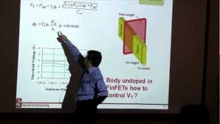
The components of a FinFET include the gate, which surrounds the fin that acts as the channel, and the source/drain at either end, typically built on a lightly doped substrate. Different types of FinFETs, such as double-gate, triple-gate, and gate-all-around (GAA), define the level of gate wrapping around the fin.
Key Characteristics
FinFETs demonstrate enhanced short-channel control, steeper subthreshold slopes, reduced drain-induced barrier lowering, and improved drive current capabilities. They also maintain low leakage currents, making them highly power-efficient, with excellent scalability for nodes under 10 nm.
Modelings
To simulate FinFET behavior effectively, compact models are imperative, especially in circuit simulators like SPICE. The analytical modeling includes Current-Voltage (I-V) characteristics and subthreshold behavior with equations derived for practical implementation.
Applications
FinFETs are pivotal in modern circuit designs, notably in low-power and high-speed digital ICs, evidenced by technologies like Intel's 22nm Tri-Gate.
In summary, FinFET technology overcomes traditional limitations found in planar MOSFET designs, delivering increased performance and efficiency for the future of electronics.
Youtube Videos


Audio Book
Dive deep into the subject with an immersive audiobook experience.
Introduction to FinFET Technology
Chapter 1 of 5
🔒 Unlock Audio Chapter
Sign up and enroll to access the full audio experience
Chapter Content
FinFET (Fin Field-Effect Transistor) is a 3D multigate transistor architecture developed to overcome the scaling limitations of planar MOSFETs below 22 nm technology node.
- The channel is formed in a vertical "fin"-like structure.
- The gate wraps around the fin on three sides, offering better electrostatic control.
Detailed Explanation
FinFETs are a new type of transistor that has a three-dimensional (3D) structure compared to traditional flat MOSFETs. When we talk about transistors, think of them as tiny switches that control electrical signals. The traditional MOSFETs can face performance issues when they become very small, particularly below 22 nm (nanometers), due to effects that can lead to leakage current and poor control of the channel. FinFETs use a fin-like vertical channel where the gate, which controls the channel, wraps around the fin, providing better control over the flow of current. This design helps to keep the signals stronger and prevents them from leaking out, especially as transistors get smaller.
Examples & Analogies
Imagine water flowing through a pipe. In traditional transistors (like MOSFETs), the controls on the pipe are just on one side, which can lead to water leaking out. In FinFETs, the controls wrap around the pipe on three sides, giving much better management over the water flow, and thereby preventing leaks.
FinFET Structure Overview
Chapter 2 of 5
🔒 Unlock Audio Chapter
Sign up and enroll to access the full audio experience
Chapter Content
- Gate: Controls the channel on three sides
- Fin: Acts as the body (channel) of the transistor
- Source/Drain: Formed at either end of the fin
- Substrate: Typically lightly doped or undoped
Detailed Explanation
The FinFET structure consists of several key components. The 'gate' is like the switch that controls whether the transistor is on or off; because it wraps around the fin on three sides, it can more effectively control the current. The 'fin' itself acts as the channel through which the electric current flows. At the ends of the fin are the 'source' and 'drain' which provide and receive the current, respectively. Finally, the substrate serves as the base upon which the transistor is built, and it is typically lightly doped or undoped to ensure better performance.
Examples & Analogies
Think of the FinFET like a multi-cam car washing station; the gate is the car wash's controls, the fin represents the car itself moving through it, and the source and drain are where water enters and exits the system. The lightly doped substrate is like the ground supporting the entire wash system.
Key Characteristics of FinFETs
Chapter 3 of 5
🔒 Unlock Audio Chapter
Sign up and enroll to access the full audio experience
Chapter Content
| Parameter | Description |
|---|---|
| Short Channel Control | Improved due to gate control on multiple sides |
| Subthreshold Slope (SS) | Steeper than planar MOSFET → better off-state control |
| Drain-Induced Barrier Lowering | Lower DIBL → reduced leakage current (DIBL) |
| Gate Capacitance (Cgg) | Increased capacitance due to multi-gate structure |
| Drive Current (Ion) | Higher due to stronger electrostatic gate control |
| Leakage Current (Ioff) | Lower, enhances power efficiency |
| Scalability | Excellent down to sub-10 nm nodes |
Detailed Explanation
FinFETs come with several advantages over traditional MOSFETs. They can control short channels better because the gate wraps around the fin. This results in a steeper subthreshold slope, enhancing control when the transistor is supposed to be 'off', minimizing unwanted electrical activity. Drain-Induced Barrier Lowering (DIBL) is less significant in FinFETs, meaning they leak less power. They also have increased gate capacitance due to their multi-gate structure, which allows for higher drive currents. Overall, they reduce leakage current, making them more energy-efficient, and can scale well down to even smaller sizes than 10 nm.
Examples & Analogies
Think of a water control system (like a dam). The dam (FinFET) is better at managing water pressure (short channel control) from different sides (three-sided gate) than a single gate (traditional MOSFET). This allows for a stronger, more stable water flow (current) into different systems while minimizing leaks (lower leakage current) and being able to adapt to even smaller pipes (scalability).
FinFET vs Planar MOSFET
Chapter 4 of 5
🔒 Unlock Audio Chapter
Sign up and enroll to access the full audio experience
Chapter Content
| Feature | Planar MOSFET | FinFET |
|---|---|---|
| Channel geometry | Flat | Raised 3D fin |
| Gate control | One-sided | Three-sided (or more) |
| Leakage current | Higher | Lower |
| Scaling capability | Limited below 22 nm | Suitable for <7 nm |
| Fabrication complexity | Lower | Higher |
Detailed Explanation
In comparing FinFETs with traditional planar MOSFETs, we notice several differences. The geometry of FinFET is raised and three-dimensional, allowing it to control current from multiple angles compared to the flat structure of planar MOSFETs. This results in lower leakage currents and better performance at smaller scales, making FinFETs preferable for advanced semiconductor technologies. However, the increased complexity of their fabrication is a trade-off that manufacturers must consider.
Examples & Analogies
Picture a flat park versus a multi-level amusement park. The flat park (planar MOSFET) allows people (electrons) to move freely but can’t control crowding well due to one entry point (one-sided gate). Meanwhile, the amusement park (FinFET) has several attractions (gates), allowing better management of visitors and less pushing (leakage). Also, the amusement park can expand to accommodate more rides (scalable to smaller nodes), albeit requiring more planning (complex fabrication).
Analytical Modeling of FinFET Behavior
Chapter 5 of 5
🔒 Unlock Audio Chapter
Sign up and enroll to access the full audio experience
Chapter Content
To analyze and simulate FinFET behavior, compact models are used in circuit simulators like SPICE.
Detailed Explanation
Analyzing FinFET behavior is essential in designing circuits. Engineers use compact models that simplify the complex workings of FinFETs, allowing them to simulate how these devices will perform in real circuits. Tools like SPICE help predict circuit behavior based on the electrical characteristics and parameters of the transistors used.
Examples & Analogies
Consider an architect using blueprints to visualize a building. The compact models in SPICE are like blueprints for electronic circuits; they help engineers see how different elements (like FinFETs) will interact without building the entire circuit from scratch.
Key Concepts
-
FinFET Technology: Advanced transistor design for overcoming limitations of traditional MOSFETs.
-
3D Multigate Structure: The architecture of FinFETs allows for better gate control over the channel.
-
Subthreshold Behavior: FinFETs exhibit a steeper subthreshold slope, enhancing their off-state control.
-
Low Leakage Current: FinFETs provide higher efficiency in electronic circuits as they minimize leakage.
-
Modeling FinFETs: Tools like SPICE enable accurate simulation of FinFET behaviors and characteristics.
Examples & Applications
An example of the effective utilization of FinFETs is in Intel's 22nm Tri-Gate technology, which demonstrates low power consumption and high-speed performance.
FinFETs are essential in modern SRAM cells, allowing for efficient memory storage with lower energy usage.
Memory Aids
Interactive tools to help you remember key concepts
Rhymes
FinFETs are neat, they won’t retreat, three-sided gates can't be beat!
Stories
Once in a world of shrinking chips, transistors battled electrostatic grips. A hero named FinFET, with three gates to call, rescued circuits, prevented the fall!
Memory Tools
Remember '3G' for FinFET: 3 gates for great control.
Acronyms
FinFET stands for Fin Field-Effect Transistor - 'Fin' represents the fin structure improving performance.
Flash Cards
Glossary
- FinFET
A type of 3D multigate transistor architecture developed to enhance performance over traditional planar MOSFETs.
- Gate Control
The mechanism by which the gate modulates the channel conductivity in a transistor.
- Short Channel Control
The ability of a transistor to manage characteristics like leakage and current drive effectively, especially as dimensions scale down.
- Subthreshold Slope
A measure of how effectively a transistor can be turned off, typically lower in FinFETs.
- DIBL
Drain-Induced Barrier Lowering, a phenomenon affecting transistor operation as channel length decreases.
- SPICE
Simulation Program with Integrated Circuit Emphasis; a standard tool for analyzing circuit behaviors.
Reference links
Supplementary resources to enhance your learning experience.