
Testbenches and Simulation
Interactive Audio Lesson
Listen to a student-teacher conversation explaining the topic in a relatable way.
Purpose of Testbenches
🔒 Unlock Audio Lesson
Sign up and enroll to listen to this audio lesson

Today, we’re going to discuss testbenches. Can anyone tell me what they think is the primary purpose of a testbench in digital design?

I think it's to check if the design works properly.
Exactly! The main purpose is verification. We want to ensure that the Design Under Test, or DUT, behaves as expected under various input conditions. What are some specific functions a testbench might perform?

It generates stimulus signals for the DUT.
Right! Stimulus generation is crucial, as it's how we apply different inputs to see how the DUT responds. Can anyone think of another function?

It monitors outputs? We need to track what's happening in the DUT.
You got it! Monitoring the outputs helps us capture and compare results. So, in summary, a testbench verifies functionality, generates stimuli, and monitors outputs.
Structure of a Basic Testbench
🔒 Unlock Audio Lesson
Sign up and enroll to listen to this audio lesson

Now that we understand the purpose, let's talk about the basic structure of a testbench. What are some key components that every testbench should have?

Does it need to have inputs and outputs?
Actually, testbenches generally don’t have traditional inputs and outputs like normal modules. They declare signals inside the module. Can you think of why this is beneficial?
Maybe because it allows testing multiple conditions without needing to connect anything externally?
Exactly! Now, what about DUT instantiation? Why is that important?
We need to link our testbench signals to the DUT.
Spot on! We instantiate the DUT within our testbench to connect to our declared signals.
What about the clock generation part?
Good point! Using an `always` block, we can create a clock signal that toggles continuously. This is essential for synchronizing operations in our design.
Self-Checking Testbenches
🔒 Unlock Audio Lesson
Sign up and enroll to listen to this audio lesson
Let's discuss self-checking testbenches. Why do you think they are useful?
Is it because they can verify the DUT without manual checking?
Exactly! Self-checking testbenches automatically compare outputs against expected results. This saves time and reduces human error. Can anyone give me an example of a system task that could help with this?
$display or $monitor?
Yes, both of those tasks are useful for output monitoring. Could you elaborate on how you might use $display in a testbench?
We could use it to print the results after applying test cases to see if the outputs are correct.
Correct! This helps to check if the results match expectations, making debugging easier.
Output Monitoring
🔒 Unlock Audio Lesson
Sign up and enroll to listen to this audio lesson
Output monitoring is crucial in our testbenches. What are some system tasks we can use for this purpose?
I remember $monitor is used to track signals continuously.
That's right! $monitor tracks changes in values and prints them out in real-time. What about $strobe?
$strobe is like $display but it shows values at the end of a time step.
Perfect! This is useful to see the final stable outputs for that time step. It helps to understand what the outputs are right at the end of each evaluation.
What would happen if there’s an error in the DUT?
We would utilize the output from our monitoring to identify issues quickly—another reason why effective monitoring is vital in design verification.
Summarizing Key Points
🔒 Unlock Audio Lesson
Sign up and enroll to listen to this audio lesson
Before we wrap up, let’s summarize what we’ve learned. What are the key points about testbenches?
They verify the DUT's behavior under various conditions.
They generate stimuli and monitor outputs without being synthesized.
Correct! And what about self-checking mechanisms?
They automate the verification process, making it easier and faster.
Absolutely! Testbenches are critical for confirming the functional correctness of designs before physical implementation.
Introduction & Overview
Read summaries of the section's main ideas at different levels of detail.
Quick Overview
Standard
Testbenches serve as essential tools for simulating and verifying hardware designs in Verilog. They help generate stimulus signals and monitor outputs, ensuring that the Design Under Test (DUT) behaves as expected. Testbenches are crucial for debugging and provide functionalities such as self-checking and output monitoring, but they are not synthesizable as hardware.
Detailed
Testbenches and Simulation in Verilog
In the design of digital systems using Verilog, writing hardware description code is only the first step. The equally essential second step is ensuring that the code effectively implements the intended design. This is achieved through testbenches, which are specialized Verilog modules created to apply test stimuli to the design under test (DUT) and validate its functionality. Here’s a breakdown of the key components and purposes of testbenches:
- Purpose of Testbenches: The primary functions of testbenches include verifying the DUT's behavior under various conditions, generating stimuli, monitoring outputs, debugging potential design flaws, and optionally automating checks against expected outputs. They leverage functionalities like output monitoring, making use of simulatable constructs to simulate various input scenarios without being synthesized into hardware.
- Basic Structure: A typical testbench has no ports and consists of several key components:
- Signal Declaration: Registers (
reg) and wires (wire) are declared to mirror the DUT’s ports. - DUT Instantiation: The DUT is instantiated, connecting its inputs and outputs to the testbench signals.
- Clock Generation: A clock signal is generated using a forever loop within an initial block.
- Stimulus Application: An initial block defines how inputs will change during simulation, including reset conditions and test cases.
-
Output Monitoring: System tasks (
$display,$monitor) are used to track values during simulation, facilitating easier debugging and analysis. - Self-checking Testbenches: These advanced testbenches include logic to automatically check expected values against actual DUT outputs, reporting pass or fail results without the need for manual verification, thus streamlining the testing process.
In summary, testbenches are indispensable for ensuring that the designed hardware modules function correctly before physical implementation, allowing for rigorous testing and debugging in a controlled simulated environment.
Youtube Videos


Audio Book
Dive deep into the subject with an immersive audiobook experience.
Purpose of Testbenches
Chapter 1 of 4
🔒 Unlock Audio Chapter
Sign up and enroll to access the full audio experience
Chapter Content
4.6.1 Purpose of Testbenches:
- Verification: The primary goal is to verify that the "Design Under Test" (DUT) behaves as expected under various input conditions.
- Stimulus Generation: Apply input signals (stimuli) to the DUT over time.
- Output Monitoring: Observe and capture the outputs of the DUT.
- Self-Checking: Optionally compare DUT outputs against expected values to automate verification.
- Debugging: Provide waveforms and messages to help debug design flaws.
- No Synthesis: Testbenches are purely for simulation and are never synthesized into hardware. Therefore, they can use non-synthesizable constructs (e.g., # delays, initial blocks, file I/O).
Detailed Explanation
Testbenches are essential tools in digital design used to simulate and validate a hardware design. Their main purpose is to verify that the design, referred to as the 'Design Under Test' (DUT), behaves correctly when subjected to different inputs. Testbenches generate these input signals over time and monitor the outputs from the DUT. They may also perform automated checks to see if the outputs match expected results, which helps in identifying design flaws. Importantly, testbenches are not intended for synthesis, meaning they won’t become part of the final hardware; instead, they can utilize constructs like timing delays that wouldn't be applicable in actual hardware design.
Examples & Analogies
Think of a testbench like a dress rehearsal for a theater play. Just as actors practice their lines and interactions to ensure they perform well for the audience, a testbench applies various scenarios to the DUT to ensure it behaves correctly before going live. The testbench checks if everything works as planned, allowing designers to catch and fix mistakes in a controlled environment without the risk of errors in the final product.
Structure of a Basic Testbench
Chapter 2 of 4
🔒 Unlock Audio Chapter
Sign up and enroll to access the full audio experience
Chapter Content
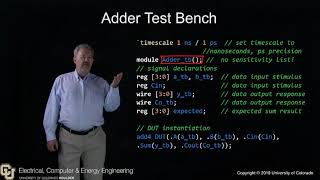
4.6.2 Structure of a Basic Testbench:
A testbench is typically a top-level Verilog module with no inputs or outputs. It instantiates the DUT and generates the necessary input waveforms.
module my_design_tb; // No ports for a testbench
// 1. Declare signals (wires/regs) for connecting to the DUT's ports
// These signals act as the inputs/outputs to your DUT
reg clk;
reg reset_n;
reg [7:0] data_in_A;
reg [7:0] data_in_B;
wire [7:0] gcd_result_out;
wire done_flag;

// 2. Instantiate the Design Under Test (DUT)
// Connect the testbench signals to the DUT's ports
GCD_Processor DUT (
.A_in(data_in_A),
.B_in(data_in_B),
.clk(clk),
.reset_n(reset_n),
.result_out(gcd_result_out),
.done_flag(done_flag)
);

// 3. Clock Generation (using an always block with forever)
parameter CLK_PERIOD = 10; // 10 ns clock period (5 ns high, 5 ns low)
initial begin
clk = 1'b0; // Initial clock value
forever #(CLK_PERIOD / 2) clk = ~clk; // Toggle clock every half period
end

// 4. Initial Block for Stimulus Application and Reset Generation
initial begin
// Apply reset (active low)
reset_n = 1'b0;
data_in_A = 8'b0;
data_in_B = 8'b0;
#(CLK_PERIOD * 2); // Hold reset for 2 clock cycles
reset_n = 1'b1; // Release reset
// Apply stimuli for GCD(48, 18) = 6
data_in_A = 8'd48;
data_in_B = 8'd18;
#(CLK_PERIOD * 1); // Wait for one clock cycle for inputs to register
// Wait for the done flag, or a maximum time
wait(done_flag);
$display("GCD(48, 18) = %0d, Expected: 6", gcd_result_out); // Display result
// Apply new stimuli for GCD(100, 75) = 25
data_in_A = 8'd100;
data_in_B = 8'd75;
#(CLK_PERIOD * 1); // Wait
wait(done_flag);
$display("GCD(100, 75) = %0d, Expected: 25", gcd_result_out);
#(CLK_PERIOD * 5); // Allow some time for final signals to settle
$finish; // End simulation
end
// 5. Monitoring Outputs (using system tasks)
initial begin
$display("Time\\tClock\\tReset\\tA_in\\tB_in\\tGCD_Result\\tDone");
$monitor("%0t\\t%b\\t%b\\t%0d\\t%0d\\t%0d\\t\\t%b", $time, clk, reset_n, data_in_A,
data_in_B, gcd_result_out, done_flag);
end
endmodule
Detailed Explanation
A basic testbench in Verilog is structured as a top-level module without any inputs or outputs. Inside this module, you define signals that will connect to the DUT's ports. This includes wires and registers necessary to drive inputs and capture outputs. The testbench instantiates the DUT and connects these signals accordingly. Additionally, it generates a clock signal, initializes the inputs, applies sequences of stimuli (which are the input values), and monitors the DUT's outputs. The testbench may also include output monitoring tasks to display information about the simulation, such as using $display and $monitor functions to continuously track the signal values during the simulation.
Examples & Analogies
Imagine writing a script for a cooking show. The script outlines the steps the chef will take to prepare a dish, including every ingredient and its quantity. In this analogy, the cooking show script represents the testbench: it provides the framework for how the dish (the DUT) is made. Just like the script directs the host's actions, the testbench manages how inputs are provided to the DUT, ensuring that it behaves correctly and produces the intended final dish (output).
System Tasks for Simulation
Chapter 3 of 4
🔒 Unlock Audio Chapter
Sign up and enroll to access the full audio experience
Chapter Content
4.6.3 System Tasks for Simulation:
- $display("format_string", arg1, ...);: Prints messages to the console during simulation. Behaves like printf in C.
- $monitor("format_string", arg1, ...);: Prints messages to the console whenever any of its arguments change value. Useful for continuously tracking signals. Only one $monitor can be active at a time.
- $strobe("format_string", arg1, ...);: Similar to $display, but prints values at the very end of the current simulation time step, after all values have stabilized. Useful for seeing final results for a given time step.
- $time: Returns the current simulation time.
- $finish;: Terminates the simulation.
- $stop;: Halts the simulation, allowing interaction (e.g., examining waveforms).
- $dumpfile("filename.vcd");, $dumpvars(0, testbench_instance);: Used to create a Value Change Dump (VCD) file for waveform viewing in a waveform viewer.
Detailed Explanation
In Verilog simulations, system tasks are predefined functions that help capture data, monitor signals, and control the simulation flow. $display is used to print messages to the simulation console, similar to how the printf function works in programming; it can be used to show any output you want at specific times during the simulation. $monitor allows continuous tracking of signals, displaying them every time there's a change in one of its arguments. $strobe differs slightly; it waits until the end of the current time step to show values, ensuring you're looking at the most stable data. The $time function is useful for tracking the current time in the simulation, while $finish and $stop control the termination of the simulation process. Lastly, $dumpfile and $dumpvars help create files that can visualize waveforms for further analysis.
Examples & Analogies
Consider system tasks like the various tools a mechanic uses while fixing a car. Just as a mechanic needs tools like a wrench (to tighten bolts) or a multimeter (to check electrical systems) to perform their job efficiently, Verilog provides system tasks to effectively manage the simulation process. $display tags along like a label maker, helping the mechanic (designer) understand what’s happening at each stage. Meanwhile, $monitor serves as an alert system, notifying whenever something changes, aiding in prompt repairs (debugging). Similarly, $dumpfile acts like a security camera, recording everything for later review. These tools are all essential to ensure the job is done correctly, just like system tasks are vital in simulation.
Self-Checking Testbenches
Chapter 4 of 4
🔒 Unlock Audio Chapter
Sign up and enroll to access the full audio experience
Chapter Content
4.6.4 Self-Checking Testbenches (Briefly):
More advanced testbenches include logic to automatically check if the DUT's outputs match expected values, reporting "PASS" or "FAIL".
// Example within initial block after getting result
if (gcd_result_out == 8'd6) begin
$display("TEST PASSED for GCD(48, 18)");
end else begin
$display("TEST FAILED for GCD(48, 18): Got %0d, Expected 6", gcd_result_out);
end
Detailed Explanation
Self-checking testbenches enhance the testing process by incorporating logic that automatically verifies the outputs of the DUT against expected results. This is done using simple conditional statements in the Verilog code. For instance, after processing an input, the testbench checks whether the DUT's output matches what is expected. If it does, a message such as 'TEST PASSED' is displayed; if not, it reports a 'TEST FAILED' along with the conflicting values. This automation reduces the manual work required to verify outcomes and ensures consistent and immediate feedback on the design's correctness.
Examples & Analogies
Imagine a quality control inspector in a factory that produces light bulbs. Each bulb comes off the line and is checked against a quality standard: it should light up when plugged in. If it works, the inspector marks it as 'passed'; if not, they label it as 'failed' and note the issue. Similarly, self-checking testbenches automate this inspection process for digital designs, automatically verifying whether the outputs meet the expected conditions. This ensures that defects are caught early and enhances the reliability of the final product.
Key Concepts
-
Purpose of Testbenches: They verify the DUT's functionality by generating stimuli and monitoring outputs.
-
Basic Structure of a Testbench: Involves signal declarations, DUT instantiation, clock generation, and stimulus application.
-
Self-Checking Mechanisms: These allow automatic verification of DUT outputs against expected results.
-
Output Monitoring: System tasks like
$display,$monitor, and$strobefacilitate tracking of outputs during simulation.
Examples & Applications
An example of a simple testbench might involve a DUT that implements a counter. The testbench would instantiate the counter, generate a clock signal, reset the counter, and apply test values sequentially.
In a self-checking testbench, after applying input values, you could check if the DUT's output matches the expected output using an if-else condition within the initial block.
Memory Aids
Interactive tools to help you remember key concepts
Rhymes
When you test, don't just guess, a testbench helps you assess!
Stories
Once there was a naive designer who spent days coding a complex system. Yet, when it came time to test, they found they forgot to verify! They quickly added a testbench, and it saved the day, catching every mistake before fabrication!
Memory Tools
DUTs Verify Stimuli Steadily (DVS) - a reminder for how testbenches work.
Acronyms
TEST
Test
Evaluate
Stimulate
Track - the steps for using a testbench.
Flash Cards
Glossary
- Testbench
A specialized module in Verilog used to simulate and verify the functionality of a Design Under Test (DUT).
- DUT (Design Under Test)
The specific module or design that is being tested and verified using a testbench.
- Simulation
The process of executing a testbench to evaluate the behavior of a DUT under specified conditions.
- Stimulus
Input signals provided to the DUT during simulation in order to observe its response.
- Output Monitoring
The practice of tracking and analyzing output signals of the DUT during simulation to verify correctness.
- SelfChecking Testbench
A testbench that includes logic to automatically verify that outputs from the DUT match expected values.
- System Tasks
Predefined functions in Verilog for managing simulation outputs and actions, such as
$displayand$monitor.
Reference links
Supplementary resources to enhance your learning experience.