
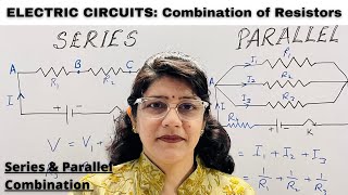
Series Combination
Enroll to start learning
You’ve not yet enrolled in this course. Please enroll for free to listen to audio lessons, classroom podcasts and take practice test.
Interactive Audio Lesson
Listen to a student-teacher conversation explaining the topic in a relatable way.
Understanding Series Circuit
🔒 Unlock Audio Lesson
Sign up and enroll to listen to this audio lesson

Today, we will explore the series combination of resistors. When resistors are placed one after the other in a circuit, we call this a series connection. Can anyone tell me how current behaves in a series circuit?

I think the current is the same through all of them, right?
Exactly! The current remains constant throughout the series circuit because there is only one path for the current to flow. This is a key feature of series circuits.

So, what happens to the voltage?
Great question! The voltage gets divided among the resistors. Each resistor has a certain voltage drop across it. Can anyone tell me how we calculate the total resistance in a series circuit?

Is it just adding them up?
Yes! The total resistance is the sum of all the individual resistances: R_total = R_1 + R_2 + R_3 + ... Remember, in series, resistance adds up!

That means more resistors will make it harder for current to flow.
Exactly right! The more resistance in the circuit, the less current will flow. This is why series circuits are important; they help control electrical conditions.
Let's summarize: In a series circuit, the current is constant, voltage divides among resistors, and total resistance increases with more resistors added.
Applying Ohm's Law to Series Circuits
🔒 Unlock Audio Lesson
Sign up and enroll to listen to this audio lesson

Now, let’s apply Ohm's Law to our series circuit example. Who remembers what Ohm’s Law states?
I remember! It says V = I × R.
That's right! If we know the total current flowing through the circuit and the total resistance, we can find the total voltage supplied by the source. Can someone give me a scenario using this?
If we had two resistors of 4 ohms and 6 ohms in series, the total resistance would be 10 ohms. If the current is 2 amps, then V would be 2 times 10, which is 20 volts, right?
Exactly! That's spot on! So, in a series circuit, knowing any two quantities allows you to find the third using Ohm's Law.
What if I wanted to find the individual voltage across one of the resistors?
Good question! The voltage across a resistor can be found by using V = I × R for that specific resistor. So, for the 4-ohm resistor with 2 amps flowing, the voltage would be 8 volts.
Got it! So, I can find the voltage drops using the same current.
Exactly! Remember, the total voltage is the sum of the voltage drops across each resistor.
Practical Applications of Series Circuits
🔒 Unlock Audio Lesson
Sign up and enroll to listen to this audio lesson
Can anyone think of examples from real life where series circuits might be used?
I think Christmas lights! If one goes out, all the others do too.
Great example! That’s because they’re wired in series. If one bulb burns out, it breaks the circuit. What other examples can we think of?
Maybe old flashlights that use multiple batteries?
Exactly! Flashlights often connect batteries in series to increase voltage. What do you think are the downsides of series circuits?
If one part fails, the entire circuit stops working.
Correct! This is a key disadvantage of series circuits. Now, who can summarize why series circuits are useful despite this drawback?
They are simple and can control current effectively, but they have the risk of complete failure if one component fails?
Well put! Series circuits have their pros and cons, and it's important to understand both.
Introduction & Overview
Read summaries of the section's main ideas at different levels of detail.
Quick Overview
Standard
The series combination of resistors shares the same current while the voltage across each resistor varies according to its resistance. This section covers the principles of series circuits, including calculations for total resistance and current flow.
Detailed
In a series combination of resistors, they are connected end to end, meaning the total current flowing through the circuit is the same at every point, while the total voltage across the resistors is the sum of the individual voltages. The formula for calculating total resistance (R_total) in a series circuit is given by R_total = R_1 + R_2 + R_3 + ... This relationship indicates that the total resistance increases with each additional resistor added in series. The significance of understanding series circuits lies in their ability to affect the behavior of the current and voltage within electric circuits, which is foundational to the study of electricity.
Youtube Videos


Audio Book
Dive deep into the subject with an immersive audiobook experience.
Introduction to Series Combination
Chapter 1 of 4
🔒 Unlock Audio Chapter
Sign up and enroll to access the full audio experience
Chapter Content
● Resistors are connected end to end.
Detailed Explanation
In a series combination, resistors are arranged in a line, one after the other. This means that the output of one resistor is connected to the input of the next. This type of arrangement allows current to flow through one resistor, and then continues to flow through the next resistor, creating a single pathway for the electrical current.
Examples & Analogies
Think about a series of people passing a message from one to another. Each person stands in a line and passes the message to the next. The only way the message can travel is through each person one at a time, similar to how current flows through each resistor in a series.
Total Resistance in Series
Chapter 2 of 4
🔒 Unlock Audio Chapter
Sign up and enroll to access the full audio experience
Chapter Content
● Total resistance: Rtotal=R1+R2+R3+… R_{\text{total}} = R_1 + R_2 + R_3 + \dots
Detailed Explanation
The total resistance in a series circuit is simply the sum of the individual resistances of each resistor connected in that series. This means if you have three resistors with values of R1, R2, and R3, you can find the total resistance (R_total) by adding them together. This property is essential for understanding how circuits behave and helps predict how much current will flow through the circuit.
Examples & Analogies
Imagine you're filling a series of buckets with water where each bucket represents a resistor. The total amount of force (or pressure) you need to fill all the buckets (total resistance) is the sum of the effort required to pour water into each individual bucket.
Current Flow in Series Circuits
Chapter 3 of 4
🔒 Unlock Audio Chapter
Sign up and enroll to access the full audio experience
Chapter Content
● Current is the same through each resistor.
Detailed Explanation
In a series circuit, the same amount of electric current flows through all the resistors because there is only one path for the current to take. When one resistor provides resistance, it slows down the current, but since there are no alternative paths, the same current continues through the next resistor.
Examples & Analogies
Think of a single-lane road lined with houses. Cars (representing current) move along that road and pass every house one after another. Regardless of how wide or narrow each house is (the resistance), every car will face the same amount of traffic.
Voltage Division in Series
Chapter 4 of 4
🔒 Unlock Audio Chapter
Sign up and enroll to access the full audio experience
Chapter Content
● Voltage divides among resistors.
Detailed Explanation
In a series circuit, the voltage supplied by the source is divided among all of the resistors in the circuit. Each resistor 'uses up' a part of the total voltage, which means the sum of the voltage drops across each resistor equals the total voltage supplied by the battery or source.
Examples & Analogies
Imagine a group of friends sharing a pizza. Each person takes a slice (the voltage drop) and shares the pizza. If the pizza represents the total voltage, then each friend’s slice represents the part of the voltage that 'belong' to each resistor. The total number of slices taken should equal the whole pizza.
Key Concepts
-
Series Circuit: A configuration where resistors are connected end to end, resulting in a single loop for current.
-
Total Resistance: The cumulative resistance of all resistors in series.
-
Voltage Division: In a series circuit, the total voltage is split among the resistors.
-
Current Consistency: The current remains the same across all components in a series circuit.
Examples & Applications
Example 1: If you have three resistors of 2Ω, 4Ω, and 6Ω in series, the total resistance will be R_total = 2Ω + 4Ω + 6Ω = 12Ω.
Example 2: In a series circuit with a voltage source of 12V and a total resistance of 12Ω, the current can be calculated using Ohm's Law, where I = V/R = 12V/12Ω = 1A.
Memory Aids
Interactive tools to help you remember key concepts
Rhymes
Series circuits connect in a line, where current stays steady, and voltage divides.
Stories
Imagine a row of friends holding hands (resistors), where everyone takes turns helping someone jump over a puddle of voltage. If one friend lets go, no one can jump - that's a series circuit!
Memory Tools
Remember 'One Path, One Current' for series circuits to recall that current is the same through all.
Acronyms
STOR
Series Total = One Resistance
meaning the total resistance equals the sum of resistances.
Flash Cards
Glossary
- Series Circuit
A circuit in which resistors are connected end to end, resulting in a single path for current flow.
- Total Resistance
The sum of all individual resistances in a series circuit.
- Voltage Drop
The reduction in voltage across a resistor in a circuit.
- Ohm's Law
A fundamental principle stating that voltage equals current multiplied by resistance (V=IR).
Reference links
Supplementary resources to enhance your learning experience.