
Ideal vs. Real Op-Amp Behavior
Interactive Audio Lesson
Listen to a student-teacher conversation explaining the topic in a relatable way.
Understanding Ideal Op-Amps
🔒 Unlock Audio Lesson
Sign up and enroll to listen to this audio lesson

Today, we're diving into the characteristics of ideal operational amplifiers, or op-amps. Can anyone tell me what you would consider an ideal op-amp?

I think it would have infinite gain and perfect performance.
That's correct! An ideal op-amp assumes infinite open-loop gain, which means even the smallest input difference results in a significantly amplified output. Remember the acronym GIO (Gain, Infinite, Output) to recall this. Can anyone describe another ideal characteristic?

Infinite input impedance means no current flows into the input terminals, right?
Exactly! This characteristic is crucial because it preserves the integrity of the signal source. Let's recapitulate: we have infinite gain, infinite input impedance, and zero output impedance. Who can remind me why zero output impedance is significant?

It means that the op-amp can drive any load without voltage drop!
Great job! So, we see that ideal op-amps simplify analysis remarkably. They enable predictable circuit behavior. Now, as we proceed, let’s contrast these characteristics with those of real op-amps.
Real Op-Amps and Their Limitations
🔒 Unlock Audio Lesson
Sign up and enroll to listen to this audio lesson

Now, let's dive into real op-amplifiers. Unlike our ideal op-amps, real op-amps display finite characteristics. Who can tell me about the finite open-loop gain?
Real op-amps have a gain that is usually in the range of 10,000 to 1,000,000?
Correct! This limitation means they may not respond linearly to very small input differences without feedback. Let’s think of the acronym TAIL (Ten-thousand to A Million, Ideal Limit). Can someone explain finite input impedance from real op-amps?

It’s high but finite, which draws some current from the signal source, affecting high-impedance applications.
Absolutely! This small current draw is essential to remember, especially when dealing with sensors. Let’s not forget non-zero output impedance as well; how does that affect circuit performance?
It can cause voltage drops when the op-amp drives large loads, right?
Exactly! So far, we’ve highlighted several critical differences. In essence, we need to keep these practical implications in mind when designing circuits.
Practical Implications of Real Op-Amps
🔒 Unlock Audio Lesson
Sign up and enroll to listen to this audio lesson
Now, let's synthesize our insights about the practical implications of real op-amps. Who can tell me why we can't always assume infinite bandwidth?
Because real op-amps have limited bandwidth. They lose gain at higher frequencies!
Right! This limitation is especially crucial in high-speed circuits, such as in communications. What's something to keep in mind regarding noise and offset voltage in real op-amps?
Noise can affect measurement accuracy, especially in precise applications, and offset voltage introduces unwanted signals?
Spot on! Choosing low-offset, low-noise op-amps is essential in instrumentation. To recap today’s class: we compared ideal versus real op-amps, covered key differences, and explored how real op-amp limitations affect design choices. Who can summarize our findings?
We learned that while ideal op-amps simplify circuit designs, real op-amps pose challenges we must consider, such as finite gain and noise generation.
Well said! Understanding these differences is vital for effective circuit design. Great job today!
Introduction & Overview
Read summaries of the section's main ideas at different levels of detail.
Quick Overview
Standard
The section explores the assumed perfect characteristics of ideal op-amps, including infinite gain and zero impedance, compared to the finite properties of real op-amps, such as noise introduction and limited bandwidth. Understanding these differences is vital for effective circuit design in practical applications.
Detailed
Detailed Summary
This section provides a comprehensive examination of the differences between ideal and real operational amplifiers (op-amps), which are fundamental components in analog electronics. It begins with an introduction to op-amp behavior, emphasizing that while ideal op-amps serve as theoretical models to simplify circuit analysis, real-world op-amps display limitations due to physical and technical constraints.
Ideal Op-Amp Characteristics
Ideal op-amps are characterized by several perfect traits:
- Infinite Open-Loop Gain: Allows for very high amplification of input differences.
- Infinite Input Impedance: No current flows into the input terminals, preserving the integrity of the signal.
- Zero Output Impedance: Ideal behavior allows for driving any load without loss of output voltage.
- Infinite Bandwidth: Able to amplify signals at any frequency without degradation.
- Zero Offset Voltage: No voltage difference when output is zero.
- Zero Noise: No extraneous signals are introduced.
- Zero Input Bias Current: Prevents additional current draw from inputs.
These characteristics are powerful for theoretical analysis, forming a basis for designing op-amp circuits.
Real Op-Amp Characteristics
In contrast, real op-amps demonstrate specific parameters that deviate from the ideal:
- Finite Open-Loop Gain: Typically between 10,000 and 1,000,000, limiting response to small input differences.
- Finite Input Impedance: Drawing small currents can impact high-impedance applications.
- Non-Zero Output Impedance: Output resistance can affect performance when managing larger loads.
- Limited Bandwidth: Significantly affects performance at high frequencies.
- Input Offset Voltage: Introduces minor unwanted output signals in precision applications.
- Noise: Results from internal circuit components affecting overall circuit accuracy.
- Input Bias Current: May introduce errors, especially in high-impedance circumstances.
Practical Implications
The section concludes with a discussion on how these deviations influence circuit design, from the practical consideration of open-loop gain limitations to the significance of power consumption in op-amps for battery-powered devices.
In summary, while ideal op-amps provide a useful framework for analysis, engineers must address the real-world limitations of op-amps to ensure effective and reliable circuit designs.
Youtube Videos


Audio Book
Dive deep into the subject with an immersive audiobook experience.
Introduction to Op-Amp Behavior
Chapter 1 of 3
🔒 Unlock Audio Chapter
Sign up and enroll to access the full audio experience
Chapter Content
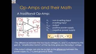
Operational amplifiers (Op-Amps) are crucial components in analog electronics, providing high-gain voltage amplification with a differential input. While the ideal op-amp is an important theoretical tool for understanding op-amp circuits, real-world op-amps exhibit behavior that deviates from the ideal characteristics due to physical limitations. In this chapter, we will examine the differences between the ideal and real op-amps, focusing on key parameters that influence their performance in practical applications.
Detailed Explanation
This chunk introduces operational amplifiers, commonly referred to as op-amps. It highlights their role in analog electronics, where they amplify voltage differences. The characteristics of an 'ideal op-amp' serve as a simplified model to facilitate understanding, while the 'real op-amp' describes actual devices that have limitations due to physical factors. The upcoming sections will explore these differences in detail and discuss their implications for practical applications.
Examples & Analogies
Think of an ideal op-amp like a perfect amplifier at a concert that magnifies even the tiniest whispers into loud sounds without any distortion. In reality, singers often sound different on stage than in practice due to microphone quality and sound system limitations. Similarly, ideal op-amps exist in theory but in practice, we work with their imperfect real counterparts.
Ideal Op-Amp Characteristics
Chapter 2 of 3
🔒 Unlock Audio Chapter
Sign up and enroll to access the full audio experience
Chapter Content
An ideal op-amp assumes perfect characteristics, making it a useful abstraction for analyzing circuits. The ideal behavior is governed by the following conditions:
● Infinite Open-Loop Gain (Aₒ): The gain is assumed to be infinitely large, meaning that even the smallest difference between the inputs will produce a significant output.
● Infinite Input Impedance: No current flows into the input terminals of an ideal op-amp. This implies that the op-amp does not load the signal source.
● Zero Output Impedance: The ideal op-amp can drive any load without experiencing a voltage drop across its output.
● Infinite Bandwidth: The op-amp can amplify signals of any frequency, with no limitations due to frequency response.
● Zero Offset Voltage: There is no voltage difference between the inverting and non-inverting inputs when the output is zero.
● Zero Noise: An ideal op-amp does not introduce any noise into the circuit.
● Zero Input Bias Current: No current is drawn by the op-amp from the input terminals. These ideal characteristics simplify analysis and allow for clear predictions of circuit behavior.
Detailed Explanation
This chunk outlines the characteristics of an ideal op-amp, which serves as a theoretical model. Each characteristic is defined: 'infinite open-loop gain' implies that even the smallest input difference generates a huge output; 'infinite input impedance' means the op-amp does not affect the circuit it measures; 'zero output impedance' allows it to drive any load without losses; 'infinite bandwidth' enables amplification across all frequencies; 'zero offset voltage' means no input voltage difference exists at zero output; 'zero noise' indicates no interference in the signal; and 'zero input bias current' shows that it draws no current from the inputs. These properties lead to straightforward circuit analysis.
Examples & Analogies
Consider an ideal op-amp akin to a perfect water pump that can deliver any amount of water without any loss, regardless of pipe size, while making no noise and consuming no power. This pump would work efficiently for any household tank, creating an easy system to manage water needs without losses. This is the theoretical perfect operation of an op-amp, which doesn't exist with real components.
Real Op-Amp Characteristics
Chapter 3 of 3
🔒 Unlock Audio Chapter
Sign up and enroll to access the full audio experience
Chapter Content
While ideal op-amps serve as an excellent foundation, real-world op-amps exhibit deviations from the ideal behavior due to physical constraints. The primary differences are:
● Finite Open-Loop Gain: Real op-amps have a finite open-loop gain, typically ranging from 10,000 to 1,000,000. As the gain is finite, the op-amp may not respond linearly to very small input differences, especially in the absence of feedback.
● Finite Input Impedance: Real op-amps have high but finite input impedance, typically in the range of MΩ. This results in a small current being drawn from the input, which can affect signal integrity.
● Non-Zero Output Impedance: While ideal op-amps have zero output impedance, real op-amps exhibit some output resistance. This can influence how the op-amp drives a load, particularly when high current is involved.
● Limited Bandwidth: Real op-amps have a limited bandwidth, meaning that they lose gain at higher frequencies. This is often characterized by a Gain-Bandwidth Product (GBW), which is the product of the op-amp's bandwidth and its gain.
● Input Offset Voltage: In practice, small voltage differences exist between the inverting and non-inverting inputs even when no input signal is applied. This offset can lead to unwanted output signals and must be minimized for precision applications.
● Noise: Real op-amps introduce noise due to internal components, including resistors and transistors. This noise can affect high-precision or high-frequency applications.
● Input Bias Current: Small amounts of current are drawn at the input terminals of real op-amps due to imperfections in the internal circuitry. This bias current can introduce errors, particularly in high-impedance circuits.
Detailed Explanation
This chunk discusses the characteristics of real op-amps compared to their ideal counterparts. It identifies key differences including finite open-loop gain, which impacts linearity; finite input impedance that draws some current, thereby affecting measurements; non-zero output impedance that can cause voltage loss under load; and limited bandwidth that restricts performance at higher frequencies. It also addresses the presence of input offset voltage, noise from internal components, and input bias current, which can lead to errors in sensitive applications.
Examples & Analogies
Imagine a real-world water pump that, while powerful, has limits. It can only lift so much water at once (finite gain), might create small leaks (input impedance affecting measurements), and can't perform well if the water is too fast (limited bandwidth). Simply put, while this pump works, it isn't perfect and has nuances that affect our garden's irrigation!
Key Concepts
-
Ideal Op-Amp: Assumes infinite gain, zero output impedance, and infinite bandwidth.
-
Real Op-Amp: Exhibits finite gain, non-zero output impedance, and limited bandwidth.
-
Practical Implications: Understanding of ideal vs. real op-amps impacts circuit design choices.
Examples & Applications
An ideal op-amp can amplify a 1 mV input signal to 1 V without any drop, while a real op-amp may only achieve this with finite gain.
In a high-impedance application, using a real op-amp may introduce errors due to input bias current.
Memory Aids
Interactive tools to help you remember key concepts
Rhymes
An op-amp that's ideal, oh so bright, infinite gain, making circuits just right.
Stories
Once upon a time, there was a magical op-amp in a lab. It had infinite abilities, never needed a power source, and never caused any noise, aiding scientists in precise measurements. But then they encountered real op-amps with limits, and it taught them to design carefully for best results!
Memory Tools
Use 'SUGAR' for remembering op-amp characteristics: S for Slew Rate (infinite), U for Unloaded (Zero output impedance), G for Gain (infinite), A for Amplitude (signal amplification), R for Resistance (infinite input impedance).
Acronyms
Remember 'GIB' for key real op-amp characteristics
for Gain (finite)
for Input impedance (high but finite)
for Bandwidth (limited).
Flash Cards
Glossary
- OpAmp
Operational Amplifier; an electronic component used to amplify voltage signals.
- Infinite OpenLoop Gain
Theoretical gain of an ideal op-amp that allows it to amplify any input difference exponentially.
- Input Impedance
Resistance seen by the input of an op-amp; ideally infinite in an ideal op-amp.
- Output Impedance
Resistance seen by the load connected to the output of an op-amp; it should ideally be zero.
- Bandwidth
The range of frequencies over which an op-amp can amplify signals effectively.
- Offset Voltage
The voltage difference between the inverting and non-inverting inputs of an op-amp when the output is zero.
- Noise
Unwanted signals introduced into a circuit that can affect performance and accuracy.
- Input Bias Current
Small amount of current that flows into the input terminals of a real op-amp.
Reference links
Supplementary resources to enhance your learning experience.