
Real Op-Amp Characteristics
Interactive Audio Lesson
Listen to a student-teacher conversation explaining the topic in a relatable way.
Finite Open-Loop Gain
🔒 Unlock Audio Lesson
Sign up and enroll to listen to this audio lesson

Let's start discussing the finite open-loop gain of real op-amps. Unlike ideal op-amps, which have infinite gain, real op-amps have a finite gain, usually between 10,000 and 1,000,000. This means they may not respond linearly to very small input differences, especially without feedback. Can anyone tell me why this matters?

If the gain is finite, wouldn't that affect how accurately the op-amp amplifies signals?
Exactly! In precision applications, the finite gain can limit the effectiveness of negative feedback. This is crucial when designing circuits. We often use feedback to improve linearity. Remember the acronym 'GIVE' - Gain Impacts Voltage Excitement!

So if we use feedback, we can actually make the circuit behave more like an ideal op-amp, right?
Yes! Feedback is key in making the op-amp work better. Let’s move on to discuss input impedance.
Finite Input Impedance
🔒 Unlock Audio Lesson
Sign up and enroll to listen to this audio lesson

Real op-amps have high but finite input impedance, generally in the MΩ range. What does this imply for the circuit?

I think it means there's a small current that flows from the signal source, potentially affecting the signal?
Correct! This small current can indeed affect signal integrity, which is particularly critical in high-impedance signal sources like sensors. Let's use the mnemonic 'HIDE' - High Impedance Draws Errors - to remember this point. Any questions?

What are some ways to minimize the impact of this current?
Using buffer stages can help. Now, let's discuss output impedance.
Non-Zero Output Impedance
🔒 Unlock Audio Lesson
Sign up and enroll to listen to this audio lesson
Unlike ideal op-amps that have zero output impedance, real op-amps have non-zero output impedance. How does this affect load driving?
It can cause voltage drops, especially when driving large loads.
Exactly! Remember the term 'LOAD': Loss Of Amplitude Due to impedance. Designing circuits that can mitigate such issues is vital.
How can we avoid this problem?
Using low-impedance op-amps or adding buffer stages can help. Let’s now look at bandwidth limitations.
Limited Bandwidth
🔒 Unlock Audio Lesson
Sign up and enroll to listen to this audio lesson
Real op-amps have limited bandwidth, meaning gain decreases at higher frequencies due to the gain-bandwidth product. Why is this important?
If the bandwidth is limited, it could restrict our ability to amplify high-frequency signals effectively?
Exactly! This limitation must be taken into account when designing high-speed circuits. The memory aid 'HIGH’ - High Impacts Gain and frequency behavior - can help you remember this. Now, let's discuss noise.
Noise and Input Bias Current
🔒 Unlock Audio Lesson
Sign up and enroll to listen to this audio lesson
Real op-amps introduce noise due to internal components like transistors. What impact does this have on high-precision applications?
The noise could lead to inaccurate readings or output signals, especially in sensitive applications, right?
Correct! Precision circuits require low-noise op-amps. Also, real op-amps exhibit input bias currents, which can affect high-impedance circuits. Keep the phrase 'BIAS' - Bias Impacts Accurate Signals - in mind!
Thanks for the helpful phrases! This makes it easier to remember these concepts.
Great! Remember that understanding these real characteristics is essential for effective circuit design.
Introduction & Overview
Read summaries of the section's main ideas at different levels of detail.
Quick Overview
Standard
Real op-amps exhibit several key characteristics that differentiate them from their ideal counterparts, including finite open-loop gain, limited bandwidth, non-zero output impedance, and noise. Understanding these differences is essential for designing effective circuits that utilize op-amps in practical applications.
Detailed
Real Op-Amp Characteristics
While ideal operational amplifiers (op-amps) provide a simplified foundation for circuit analysis, real op-amps display behaviors that deviate from these ideal traits because of physical constraints. The key real-life limitations discussed include finite open-loop gain, which typically ranges from 10,000 to 1,000,000, limiting linear response to small input differences. Additionally, real op-amps possess finite input impedance (usually in the MΩ range), withdrawing small input current that can affect signal integrity.
Output impedance is also non-zero, leading to voltage drops when driving large loads. Moreover, the bandwidth of real op-amps is limited; they experience a gain-bandwidth product, which indicates that as frequency increases, gain decreases. Input offset voltage, a slight voltage difference between the inverting and non-inverting terminals, can produce unwanted output signals, and real op-amps introduce some noise from internal components. Finally, real op-amps draw input bias currents, which can introduce errors in high-impedance circuits.
Understanding these characteristics is crucial for designing effective circuits that align with the necessary requirements of real-world applications.
Youtube Videos


Audio Book
Dive deep into the subject with an immersive audiobook experience.
Finite Open-Loop Gain
Chapter 1 of 5
🔒 Unlock Audio Chapter
Sign up and enroll to access the full audio experience
Chapter Content
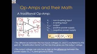
Real op-amps have a finite open-loop gain, typically ranging from 10,000 to 1,000,000. As the gain is finite, the op-amp may not respond linearly to very small input differences, especially in the absence of feedback.
Detailed Explanation
In contrast to ideal op-amps, which are assumed to have infinite open-loop gain, real op-amps have a limited gain. This means they can't amplify very small differences in input voltage as effectively. The gain value typically ranges from 10,000 to 1,000,000, which can significantly impact their performance in some applications. Thus, when using real op-amps, especially without feedback arrangements, the output may not accurately reflect the intended amplification, leading to less linear responses at minimal input differences.
Examples & Analogies
Think of a microphone that only amplifies sounds above a certain volume. If someone speaks too softly, the microphone may not pick it up or may distort it. Similarly, real op-amps may not effectively amplify very small voltage differences, leading to potential inaccuracies in signal amplification.
Finite Input Impedance
Chapter 2 of 5
🔒 Unlock Audio Chapter
Sign up and enroll to access the full audio experience
Chapter Content
Real op-amps have high but finite input impedance, typically in the range of MΩ. This results in a small current being drawn from the input, which can affect signal integrity.
Detailed Explanation
Real op-amps have high input resistance (impedance), which means they draw very little current from the connected input sources. However, unlike ideal op-amps which draw no current at all, real op-amps do draw a small amount of current. This can potentially disrupt the integrity of the signal, especially if the signal source is also high impedance. For example, if you connect the op-amp to a sensor that has a delicate output, the small current drain might change the sensor's output, leading to inaccurate results.
Examples & Analogies
Imagine using a sponge to soak up water. An ideal sponge would absorb everything without leaving any behind, while a real sponge might soak up some water but also take a little from the surrounding area – which can alter the amount of water left behind. In a similar way, real op-amps affect the signals they measure or amplify due to the small current they draw in.
Non-Zero Output Impedance
Chapter 3 of 5
🔒 Unlock Audio Chapter
Sign up and enroll to access the full audio experience
Chapter Content
While ideal op-amps have zero output impedance, real op-amps exhibit some output resistance. This can influence how the op-amp drives a load, particularly when high current is involved.
Detailed Explanation
In an ideal scenario, the output of an op-amp would have zero impedance, meaning it could drive any load without affecting the output voltage. However, real op-amps have some degree of output impedance, which introduces a resistance factor that can affect performance, especially under high current conditions. When connecting an op-amp to various loads, this output impedance can create voltage drops or result in less current being delivered than expected. This becomes an important factor when designing circuits that require precise voltage and current characterization.
Examples & Analogies
Think of how a garden hose works. If the hose is completely unrestricted, water flows freely. But if the hose has kinks or is too thin, the water flow (representing the output of the op-amp) will be restricted. Similarly, the output impedance of real op-amps can restrict how effectively they deliver power to a load.
Limited Bandwidth
Chapter 4 of 5
🔒 Unlock Audio Chapter
Sign up and enroll to access the full audio experience
Chapter Content
Real op-amps have a limited bandwidth, meaning that they lose gain at higher frequencies. This is often characterized by a Gain-Bandwidth Product (GBW), which is the product of the op-amp's bandwidth and its gain.
Detailed Explanation
While ideal op-amps can amplify signals of any frequency without losing gain, real op-amps can only maintain their gain over a limited range of frequencies. The product of the op-amp's bandwidth (range of frequencies it can handle) and its gain is called the Gain-Bandwidth Product (GBW). As you try to amplify higher frequency signals, the gain of the op-amp will decrease. Thus, selecting the right op-amp for specific frequency applications becomes critical, as it ensures that the op-amp can adequately amplify the signals of interest without significant loss.
Examples & Analogies
Imagine trying to tune into a radio station while driving through a hilly area. Lower frequencies might come in clear, but as you shift to higher frequencies, the signal gets weaker and can even be lost altogether. Just like that, real op-amps may effectively amplify lower frequency signals but struggle at higher ones.
Input Bias Current
Chapter 5 of 5
🔒 Unlock Audio Chapter
Sign up and enroll to access the full audio experience
Chapter Content
Small amounts of current are drawn at the input terminals of real op-amps due to imperfections in the internal circuitry. This bias current can introduce errors, particularly in high-impedance circuits.
Detailed Explanation
Input bias current refers to the tiny current that flows into the input terminals of a real op-amp. This occurs because of the imperfections within the op-amp's internal design. In precision applications, even these small currents can cause significant errors, especially in high-impedance circuits where the effects of additional current can lead to unintended changes in voltage levels.
Examples & Analogies
Picture holding a beach ball in a gentle breeze. If someone stands too close and pushes against the ball lightly, it can easily veer off course. Similarly, even a small defined current at the input terminal of an op-amp, like the bias current, can cause larger changes in the output, especially in sensitive circuits.
Key Concepts
-
Finite Open-Loop Gain: The gain that limits linear response to small input differences in real op-amps.
-
Finite Input Impedance: The input resistance which draws small current, potentially affecting signal integrity.
-
Non-Zero Output Impedance: The impedance influencing voltage drops when driving large loads.
-
Limited Bandwidth: The constraint on frequency response affecting high-speed circuit effectiveness.
-
Input Offset Voltage: Voltage difference present between input terminals that may produce unwanted signals.
-
Noise: Internal signals that can lead to inaccuracies in measurements.
-
Input Bias Current: Current drawn from inputs that may cause errors in signal processing.
Examples & Applications
In a sensor application, the finite input impedance of a real op-amp may draw sufficient current to affect measurement accuracy.
A high-frequency amplifier circuit will struggle to maintain gain due to the limited bandwidth of the op-amp.
Memory Aids
Interactive tools to help you remember key concepts
Rhymes
Finite gain is not the same, it needs feedback to play the game!
Stories
Imagine a singer who can only reach a certain note - this is like real op-amps with limited gain. They can't hit the high notes without a little help, just like how feedback helps op-amps amplify signals accurately.
Memory Tools
Remember 'BIAS' for input bias current - Bias Impacts Accurate Signals.
Acronyms
Use 'HIDE' - High Impedance Draws Errors - to remember finite input impedance.
Flash Cards
Glossary
- Finite OpenLoop Gain
The limited gain that real op-amps exhibit, typically between 10,000 and 1,000,000.
- Finite Input Impedance
The high but non-infinite resistance at the input terminals of real op-amps, causing small input current to flow.
- NonZero Output Impedance
The presence of some output resistance in real op-amps, affecting how they drive loads.
- Limited Bandwidth
The restricted frequency range over which real op-amps maintain their gain.
- Input Offset Voltage
The small voltage difference between input terminals even when no input signal is applied.
- Noise
Unwanted electrical signals introduced by components within the op-amp, potentially affecting accuracy.
- Input Bias Current
Small current drawn from the input terminals due to imperfections in the op-amp circuitry.
Reference links
Supplementary resources to enhance your learning experience.