
Non-Inverting Amplifier Configuration
Interactive Audio Lesson
Listen to a student-teacher conversation explaining the topic in a relatable way.
Introduction to Non-Inverting Amplifiers
🔒 Unlock Audio Lesson
Sign up and enroll to listen to this audio lesson

Today, we are discussing the non-inverting amplifier configuration. Can anyone tell me how it differs from an inverting amplifier?

Isn't the non-inverting amplifier supposed to keep the output in phase with the input?
That's correct! In fact, the non-inverting amplifier amplifies the input signal without inversion. This makes it particularly useful in many applications. Let's remember this by using the acronym 'NIA', which stands for Non-Inverting Amplifier.

What is the general gain equation for this configuration?
The voltage gain is given by \( A_v = 1 + \frac{R_f}{R_{in}} \). For example, if we decide to have R₁ at 10 kΩ and R₂ at 100 kΩ, how do you think we'd calculate the gain?

It would be \( 1 + \frac{100k}{10k} \) which equals 11, right?
Exactly! So the output will be 11 times the input while remaining in phase. That’s a fundamental aspect of non-inverting amplifiers.
Design Considerations of Non-Inverting Amplifiers
🔒 Unlock Audio Lesson
Sign up and enroll to listen to this audio lesson

Let's dive into some design considerations for non-inverting amplifiers. Can anyone tell me why it is important that the gain is always 1 or greater?

Is it because we want to make sure that the output is not less than the input?
Exactly, we want to amplify the signal. The higher the input impedance, the better it is for not affecting the source circuit. Does anyone remember what applications benefit from this high input impedance?
Voltage followers!
Right! Voltage followers are excellent examples where we want to keep the voltage level stable without loading the signal source.
Advantages of Non-Inverting Amplifiers
🔒 Unlock Audio Lesson
Sign up and enroll to listen to this audio lesson
Now, let’s talk about the advantages that non-inverting amplifiers have. What do you think happens with input impedance?
It must be high, which helps in not disturbing the circuit that feeds it.
Correct! High input impedance is one of the biggest advantages. Can anyone think of a scenario where this feature is particularly beneficial?
Maybe in sensor applications where we don't want to lower the signal?
Great example! In sensors, maintaining the integrity of the signal is crucial. Remember, always look for use cases where high input impedance is necessary.
Recap and Key Takeaways
🔒 Unlock Audio Lesson
Sign up and enroll to listen to this audio lesson
So we’ve covered a lot today! Can someone summarize what we learned about non-inverting amplifiers?
They amplify the signal without inversion and have a gain that is always greater than or equal to one.
And they provide high input impedance, useful for voltage followers and certain buffering applications.
Exactly right! I hope everyone feels confident with non-inverting amplifiers. Remember our acronym 'NIA' to recall their purpose and properties.
Introduction & Overview
Read summaries of the section's main ideas at different levels of detail.
Quick Overview
Standard
In this section, we explore the non-inverting amplifier configuration, detailing its circuit description, gain equation, design considerations, and advantages. It amplifies the input signal in-phase and is characterized by a high input impedance, making it ideal for certain applications.
Detailed
Non-Inverting Amplifier Configuration
The non-inverting amplifier configuration utilizes negative feedback to amplify an input signal without inverting it. This configuration is widely used in various applications due to its high input impedance and ability to maintain the phase of the input signal.
Key Components and Circuit Description
- Input Signal: The input is applied directly to the non-inverting terminal of the Op-Amp.
- Feedback Resistor: Resistor R₂ connects the output to the inverting terminal, creating feedback.
- Ground Reference: The inverting terminal has a resistor (R₁) connected to ground, forming the other part of the feedback loop.
Ideal Gain Equation
The voltage gain of the non-inverting amplifier is defined by the formula:
\[ A_v = 1 + \frac{R_f}{R_{in}} \]
Where:
- \( R_f \) is the feedback resistor (R₂).
- \( R_{in} \) is the resistor that connects the inverting terminal to ground (R₁).
Design Considerations
- The gain is always 1 or greater.
- The output voltage is in phase with the input signal, which is critical in many applications.
Advantages
- High Input Impedance: Prevents loading the signal source.
- Ideal for Buffering: Apt for voltage followers that require maintaining the voltage level without loading the previous stage.
Examples
To illustrate, if R₁ = 10 kΩ and R₂ = 100 kΩ, the gain would be:
\[ A_v = 1 + \frac{100k}{10k} = 11 \]
Thus, the output signal will be 11 times the input and will remain in-phase.
Youtube Videos
Audio Book
Dive deep into the subject with an immersive audiobook experience.
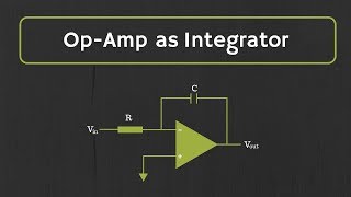
Circuit Description
Chapter 1 of 5
🔒 Unlock Audio Chapter
Sign up and enroll to access the full audio experience
Chapter Content
The input signal is applied to the non-inverting terminal of the Op-Amp.
The inverting terminal is connected to the output through resistor R₂.
The non-inverting terminal is connected to the input signal directly.
Detailed Explanation
In a non-inverting amplifier configuration, the input signal is delivered to the non-inverting terminal of the operational amplifier (Op-Amp). Unlike an inverting amplifier, where the input goes to the inverting terminal, the non-inverting setup keeps the signal's phase intact. The inverting terminal is connected to the output via a feedback resistor (R₂), which is crucial for setting the gain of the amplifier.
Examples & Analogies
Think of it like a conversation where the speaker (input signal) can directly express their thoughts (signal) without any distortion. The person listening (the Op-Amp) retains the original message and makes it louder for everyone in the group (the output).
Ideal Gain Equation
Chapter 2 of 5
🔒 Unlock Audio Chapter
Sign up and enroll to access the full audio experience
Chapter Content
The voltage gain of the non-inverting amplifier is given by the equation:
Av=1+RfRin
Where:
○ R_f is the feedback resistor (R₂).
○ R_{in} is the resistor between the inverting terminal and ground (R₁).
Detailed Explanation
The equation for the voltage gain (Av) in a non-inverting amplifier is expressed as Av = 1 + (R_f/R_in). This means the amplifier's gain is always at least 1, which ensures that the output signal is as strong as or stronger than the input signal. R_f represents the feedback resistor that determines how much of the output is fed back to the inverting terminal. R_in is the resistor connected to the ground, contributing to the overall resistance ratio that sets the gain.
Examples & Analogies
Imagine you are amplifying the sound in a room. The gain is like a volume control. Even if you set the volume to '1' (no amplification), you can still hear the sound clearly – that is the minimum gain! Increasing the volume (changing R_f) makes the sound even louder, ensuring everyone hears perfectly.
Design Considerations
Chapter 3 of 5
🔒 Unlock Audio Chapter
Sign up and enroll to access the full audio experience
Chapter Content
The gain is always greater than or equal to 1.
The output voltage is in-phase with the input signal.
Detailed Explanation
In designing a non-inverting amplifier, it's essential to note that the gain will never be less than 1. This feature is particularly beneficial because it ensures that the output signal matches the phase of the input signal (in-phase). Unlike inverting amplifiers, where the output is a mirror image of the input, non-inverting amplifiers maintain the input signal's orientation, which is often desirable in many applications.
Examples & Analogies
Think of it like a light switch. When you flip the switch on (input), the light (output) turns on, projecting the same light in the same direction without flipping it upside down. The light isn't dimmed (gain >= 1); it either stays the same or gets brighter.
Advantages
Chapter 4 of 5
🔒 Unlock Audio Chapter
Sign up and enroll to access the full audio experience
Chapter Content
○ Provides a high input impedance.
○ Ideal for use in voltage follower and buffering applications.
Detailed Explanation
One of the key advantages of a non-inverting amplifier is its high input impedance, which means it draws very little current from the input source. This is particularly useful in circuits where the input signal could be affected by loading, ensuring that the source remains undisturbed. Additionally, this configuration is perfect for voltage followers or buffers, where you want to protect the input from loading effects while amplifying the signal.
Examples & Analogies
Picture this scenario: you have a delicate plant (input source) that needs watering (signal). If you use a heavy watering can (low impedance), you might disturb the plant. But using a gentle misting spray (high impedance input) allows you to provide moisture without damaging the plant, keeping it healthy and thriving while ensuring it gets the help it needs.
Example Calculation
Chapter 5 of 5
🔒 Unlock Audio Chapter
Sign up and enroll to access the full audio experience
Chapter Content
Suppose R₁ = 10 kΩ and R₂ = 100 kΩ. The voltage gain will be:
Av=1+100k10k=11
Thus, the output will be 11 times the input and in-phase.
Detailed Explanation
In this specific example, if R₁ is set to 10 kΩ and R₂ to 100 kΩ, the voltage gain can be calculated using the formula: Av = 1 + (R_f/R_in), resulting in a gain of 11. This means for any input voltage, the output voltage will be 11 times stronger while maintaining the same phase. This illustrates how changing R_f and R_in influences the output signal's strength.
Examples & Analogies
Imagine amplifying a whisper in a large room. If you're able to take that whisper (input) and project it 11 times louder (output), everyone in the room hears the message clearly and at the same time, without any jumbled or misaligned words.
Key Concepts
-
Gain Equation: The formula \( A_v = 1 + \frac{R_f}{R_{in}} \) represents the voltage gain in a non-inverting amplifier.
-
High Input Impedance: A characteristic of non-inverting amplifiers allowing them to not load the circuit feeding them.
-
In-Phase Output: The output signal remains in-phase with the input signal, which is essential for many applications.
Examples & Applications
To illustrate, if R₁ = 10 kΩ and R₂ = 100 kΩ, the gain would be:
\[ A_v = 1 + \frac{100k}{10k} = 11 \]
Thus, the output signal will be 11 times the input and will remain in-phase.
Memory Aids
Interactive tools to help you remember key concepts
Rhymes
Non-inverting, signals shine, outputs free of phase decline.
Stories
Imagine a water pipe where you want water to flow without altering its pressure. The non-inverting amplifier is like that pipe, handling the water flow steadily without interference.
Memory Tools
Use 'NIAP' to remember: Non-Inverting Amplifier Phase.
Acronyms
NIA = Non-Inverting Amplifier with gain greater than or equal to 1.
Flash Cards
Glossary
- NonInverting Amplifier
An amplifier configuration that outputs an amplified signal that is in-phase with the input.
- Feedback Resistor
A resistor used to create feedback in the amplifier circuit, helping to determine the gain.
- Input Impedance
The impedance that an input signal sees at the amplifier input terminal, ideally high in a non-inverting amplifier.
- Voltage Follower
A specific type of non-inverting amplifier which outputs the same voltage as the input, providing high input impedance.
Reference links
Supplementary resources to enhance your learning experience.